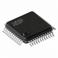
TDA8007BHL/C3,118 NXP Semiconductors, TDA8007BHL/C3,118 Datasheet - Page 28

TDA8007BHL/C3,118
Manufacturer Part Number
TDA8007BHL/C3,118
Description
IC INTERFACE CARD MP 48-LQFP
Manufacturer
NXP Semiconductors
Datasheet
1.TDA8007BHLC3118.pdf
(51 pages)
Specifications of TDA8007BHL/C3,118
Controller Type
Multiprotocol IC Card Interface
Interface
Parallel
Voltage - Supply
2.7 V ~ 6 V
Current - Supply
315mA
Operating Temperature
-40°C ~ 85°C
Mounting Type
Surface Mount
Package / Case
48-LQFP
Maximum Operating Temperature
+ 85 C
Minimum Operating Temperature
- 40 C
Mounting Style
SMD/SMT
Lead Free Status / RoHS Status
Lead free / RoHS Compliant
Other names
568-3520-2
935272525118
TDA8007BHLBE-T
935272525118
TDA8007BHLBE-T
Available stocks
Company
Part Number
Manufacturer
Quantity
Price
Company:
Part Number:
TDA8007BHL/C3,118
Manufacturer:
NXP Semiconductors
Quantity:
10 000
NXP Semiconductors
TDA8007BHL
Product data sheet
8.2.3.6 Power Control Registers (PCR)
Table 29.
Clock switching constraints:
The power control registers PCR1 and PCR2:
To deactivate the card, only bit START should be reset.
Table 30.
[1]
Bit
4
3
2 to 0
PCR7
•
•
•
•
•
•
•
•
f
In case of f
pin XTAL1
When switching from
(bits AC1 and AC0 must remain the same). When switching from
clock stopped or vice verse, only bits CST and SHL must be changed
When switching from
command and the effective frequency change on CLK (the fastest switching time is
from
vice verse)
It is necessary to survey the bit CLKSW in register MSR before re-transmitting
commands to the card.
Start or stop card sessions
Read from or write to auxiliary card contacts C4 and C8
Are available only for cards 1 or 2.
Register value at reset: all bits are cleared after reset.
int
7
is the frequency delivered by the internal oscillator
1
⁄
2
Description of CCRx bits
Register PCR1 and PCR2 (address 07H; read and write)
f
6
PCR6
XTAL
Symbol
CST
SC
AC
CLK
All information provided in this document is subject to legal disclaimers.
to
= f
1
⁄
2
XTAL
f
int
Rev. 8 — 11 January 2011
5
C8
or vice verse, the best for duty cycle is from
, the duty cycle must be ensured by the incoming clock signal on
1
1
⁄
⁄
n
n
f
f
XTAL
XTAL
Description
Clock Stop (CST). In the case of an asynchronous card,
bit CST defines whether the clock to the card is stopped or not; if
bit CST is reset, then the clock is determined by bits AC0, AC1
and AC2.
Synchronous Clock (SC). In the event of a synchronous card,
then contact CLK is the copy of the value of bit SC; in reception
mode, the data from the card is available to bit UR0 after a read
operation of register URR; in transmission mode, the data is
written on the I/O line of the card when register UTR has been
written to and remains unchanged when another card is
selected.
Alternating Clock (AC). All frequency changes are
synchronous, thus ensuring that no spikes or unwanted pulse
widths occur during changes.
000 = f
001 =
010 =
011 =
100 to 111 =
to
to
4
C4
…continued
1
1
1
1
1
⁄
⁄
XTAL
2
2
⁄
⁄
⁄
8
2
4
f
f
f
f
f
XTAL
XTAL
XTAL
XTAL
XTAL
1
⁄
or vice verse, only bit AC2 must be changed
or vice verse, a delay can occur between the
2
f
int
3
1V8
2
RSTIN
Multiprotocol IC card interface
TDA8007BHL
[1]
1
3V/5V
1
1
⁄
⁄
8
n
© NXP B.V. 2011. All rights reserved.
f
f
XTAL
XTAL
to
to
0
START
1
1
⁄
⁄
2
2
f
f
int
XTAL
28 of 51
or
to


