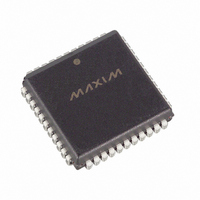
DS2181AQ/T&R Maxim Integrated Products, DS2181AQ/T&R Datasheet - Page 22

DS2181AQ/T&R
Manufacturer Part Number
DS2181AQ/T&R
Description
IC TXRX CEPT PRIMARY RATE 44PLCC
Manufacturer
Maxim Integrated Products
Type
Transceiverr
Datasheet
1.DS2181A.pdf
(32 pages)
Specifications of DS2181AQ/T&R
Number Of Drivers/receivers
1/1
Protocol
CEPT
Voltage - Supply
4.5 V ~ 5.5 V
Mounting Type
Surface Mount
Package / Case
44-LCC, 44-PLCC
Lead Free Status / RoHS Status
Contains lead / RoHS non-compliant
Available stocks
Company
Part Number
Manufacturer
Quantity
Price
Company:
Part Number:
DS2181AQ/T&RDS2181AQ/T&R
Manufacturer:
Maxim Integrated
Quantity:
10 000
CECR: CRC4 ERROR COUNT REGISTER Figure 21
(MSB)
FECR: FRAME ERROR COUNT REGISTER Figure 22
(MSB)
ERROR LOGGING
The BVCR, CECR and FECR contain 8-bit binary up counters which increment on individual bipolar
violations, CRC4 code word errors (when CCR.2 = 1), and word errors in the frame alignment signal.
Each counter saturates at 255. Once saturated, each following error occurrence will generate an interrupt
(RIMR.0 = 1) until the register is reprogrammed to a value other than FF (hex). Presetting the registers
allows the user to establish specific error count thresholds; the counter will count up to saturation from
the preset value. The BVCR increments at all times (regardless of sync status), except when HDB3 code
words are received with CCR.4=1. CECR and FECR increments are disabled whenever resync is in
progress (RLOS high).
ALARM OUTPUTS
Alarm conditions are also reported real time at alarm outputs. These outputs can be used with off-chip
logic to complement the on-chip error reporting capability of the DS2181A. In the hardware mode, they
are the only alarm reporting means available.
RLOS
The RLOS output indicates the status of the receive synchronizer. When high, frame, CAS multiframe
and/or CRC4 multiframe synchronization is in progress. A high-low transition indicates resync is
complete. The RLOS bit (RSR.1) is a latched version of the RLOS output.
RRA
The remote alarm output transitions high when a remote alarm is detected. A high-low transition indicates
the alarm condition has been cleared. The alarm condition is defined as bit 3 of time slot 0 set for three
consecutive non-align frames. The alarm state is cleared when bit 3 has been clear for three consecutive
non-align frames. The RRA bit (RSR.7) is a latched version of the RRA Output.
RBV
RBV pulses high when the accused bit emerges at RSER. RBV will return low when RCLK goes low.
Bipolar violations are also logged in the BVCR. The RBV pin provides a pulse for every violation which
can be counted externally.
SYMBOL
SYMBOL
CRC7
FE7
CRC7
CRC0
FE7
FE0
CRC6
FE6
POSITION
POSITION
BVCR.7
BVCR.0
FECR.7
FECR.0
CRC5
FE5
NAME AND DESCRIPTION
MSB of CRC4 error count.
LSB of CRC4 error count.
NAME AND DESCRIPTION
MSB of frame error count.
LSB of frame error count.
CRC4
FE4
22 of 32
CRC3
FE3
CRC2
FE2
CRC1
FE1
(LSB)
(LSB)
CRC0
DS2181A
FE0


