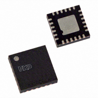
PCA9502BS,151 NXP Semiconductors, PCA9502BS,151 Datasheet - Page 4

PCA9502BS,151
Manufacturer Part Number
PCA9502BS,151
Description
IC I/O EXPANDER I2C/SPI 24HVQFN
Manufacturer
NXP Semiconductors
Datasheet
1.PCA9502BS151.pdf
(25 pages)
Specifications of PCA9502BS,151
Package / Case
24-VQFN Exposed Pad, 24-HVQFN, 24-SQFN, 24-DHVQFN
Interface
I²C, SPI
Number Of I /o
8
Interrupt Output
No
Frequency - Clock
400kHz
Voltage - Supply
2.3 V ~ 3.6 V
Operating Temperature
-40°C ~ 85°C
Mounting Type
Surface Mount
Logic Family
PCA
Number Of Lines (input / Output)
14 / 11
Operating Supply Voltage
3.3 V / 2.5 V
Power Dissipation
300 mW
Operating Temperature Range
- 40 C to + 85 C
Logic Type
I/O Expander
Mounting Style
SMD/SMT
Number Of Input Lines
14
Number Of Output Lines
11
Output Current
+/- 10 mA
Output Voltage
2.4 V
Lead Free Status / RoHS Status
Lead free / RoHS Compliant
Lead Free Status / RoHS Status
Lead free / RoHS Compliant, Lead free / RoHS Compliant
Other names
568-3635
935281363151
PCA9502BS-S
935281363151
PCA9502BS-S
NXP Semiconductors
7. Functional description
PCA9502_3
Product data sheet
7.1 Hardware reset, Power-On Reset (POR) and software reset
Table 2.
[1]
The device interfaces to a host through either I
I2C/SPI pin), and provides the host with eight programmable GPIO pins.
These three reset methods are identical and will reset the internal registers as indicated in
Table
Table 3
Table 3.
Table 4
Table 4.
Symbol
IRQ
GPIO0
GPIO1
GPIO2
GPIO3
GPIO4
GPIO5
GPIO6
GPIO7
V
V
Register
I/O direction
I/O interrupt enable
I/O control
Signal
I/Os
IRQ
SS
SS
See
3.
Section 7.1 “Hardware reset, Power-On Reset (POR) and software reset”
summarizes the state of registers after reset.
summarizes the state of hardware pins after reset.
Pin description
Registers after reset
Signals after reset
Pin
12
13
14
15
16
18
19
20
21
10, 17,
23
center
pad
Rev. 03 — 13 October 2006
Type Description
O
I/O
I/O
I/O
I/O
I/O
I/O
I/O
I/O
-
-
Reset state
all bits cleared
all bits cleared
all bits cleared
Reset state
inputs
HIGH by external pull-up
…continued
Interrupt (open-drain, active LOW). Interrupt is enabled when
interrupt sources are enabled in the I/O Interrupt Enable register
(IOIntEna). The interrupt condition is the change of state of the
input pins. An external resistor (1 k for 3.3 V, 1.5 k for 2.5 V)
must be connected between this pin and V
programmable I/O pin
programmable I/O pin
programmable I/O pin
programmable I/O pin
programmable I/O pin
programmable I/O pin
programmable I/O pin
programmable I/O pin
ground
The center pad on the back side of the HVQFN24 package is
metallic and should be connected to ground on the printed-circuit
board.
8-bit I/O expander with I
2
C-bus or SPI interface (selectable through
2
DD
C-bus/SPI interface
PCA9502
.
© NXP B.V. 2006. All rights reserved.
4 of 25


