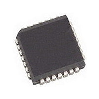
AMIS49587C5871RG ON Semiconductor, AMIS49587C5871RG Datasheet - Page 17

AMIS49587C5871RG
Manufacturer Part Number
AMIS49587C5871RG
Description
IC MODEM PLC 50/60MHZ 28PLCC
Manufacturer
ON Semiconductor
Specifications of AMIS49587C5871RG
Baud Rates
Selectable
Interface
SCI
Voltage - Supply
3 V ~ 3.6 V
Mounting Type
Surface Mount
Package / Case
28-PLCC
Number Of Transmitters
1
Power Supply Requirement
Single
Package Type
PLCC
Operating Temperature Classification
Commercial
Mounting
Surface Mount
Pin Count
28
Operating Temperature (max)
70C
Dual Supply Voltage (typ)
Not RequiredV
Dual Supply Voltage (max)
Not RequiredV
Dual Supply Voltage (min)
Not RequiredV
Lead Free Status / RoHS Status
Lead free / RoHS Compliant
Data Format
-
Lead Free Status / Rohs Status
Compliant
Available stocks
Company
Part Number
Manufacturer
Quantity
Price
Company:
Part Number:
AMIS49587C5871RG
Manufacturer:
ON
Quantity:
3 400
Company:
Part Number:
AMIS49587C5871RG
Manufacturer:
ON Semiconductor
Quantity:
10 000
CLOCK AND CONTROL
Oscillator
crystal of 24 MHz. XIN is the input to the oscillator inverter
gain stage and XOUT is the output.
Figure 12 must be connected to the oscillator pins. For a
crystal requiring a parallel capacitance of 20 pF C
around 30 pF. (Values of capacitors are indicative only and
are given by the crystal manufacturer). To guarantee startup
the series loss resistance of the crystal must be smaller than
80 W.
the clock symmetry.
Zero Crossing Detector
or 60 Hz. This pin is used to detect the crossing of the zero
voltage on one selected phase. This information is used,
after filtering with the internal PLL, to synchronize frames
with the mains frequency. In case of direct connection to the
mains, the use of a series resistor of 1 MW is advised in order
to limit the current flowing through the external protection
The transmitting has the following characteristics:
The oscillator works with a standard parallel resonance
For correct functioning the external circuit illustrated in
A parallel resistor R
M50HZ_IN is the mains frequency analog input pin − 50
♦
♦
♦
IDLE (mark)
Half duplex.
Standard NRZ format.
Start bit, 8 data bits and 1 stop bit.
Figure 12. Placement of the Capacitors and Crystal with Clock Signal Generated Internally
X
Start
t
BIT
= 1 MW is recommended to improve
XTAL _IN
LSB
D0
C
X
V
SSA
D1
R
D2
X
X
Figure 13. Data Format
24 MHz
must be
http://onsemi.com
V
SSA
D3
8 data bits
1 character
XTAL _ OUT
C
17
X
diodes. The zero crossing detector output is logic zero when
the input is lower than the falling threshold level and a logic
one when the input is higher than the rising threshold level.
The falling edges of the output of the zero crossing detector
are filtered by a period between 0.5 ms and 1 ms. Rising
edges are not filtered.
COMMUNICATION CONTROLLER
Serial Communication Interface (SCI)
communicate with a UART = Universal Asynchronous
Receiver
Communication Interface Adapter and all other chips that
employ standard asynchronous serial communication. The
serial communication interface allows only half duplex
communication.
D4
The SCI allows asynchronous communication. It can
♦
♦
♦
19200 and 38400 baud).
Hardware programmable baud−rate (4800, 9600,
0−5 V levels with open drain for TxD.
0−5 V levels for RxD and T_REQ.
D5
Transmitter,
D6
D7
MSB
ACIA
Stop
t
BIT
=
IDLE (mark)
Asynchronous


