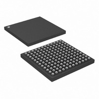
DS33X11+ Maxim Integrated Products, DS33X11+ Datasheet - Page 233

DS33X11+
Manufacturer Part Number
DS33X11+
Description
IC MAPPING ETHERNET 144CSBGA
Manufacturer
Maxim Integrated Products
Datasheet
1.DS33X11.pdf
(375 pages)
Specifications of DS33X11+
Applications
Data Transport
Interface
SPI
Voltage - Supply
1.8V, 2.5V, 3.3V
Package / Case
144-CSBGA
Mounting Type
Surface Mount
Lead Free Status / RoHS Status
Lead free / RoHS Compliant
- Current page: 233 of 375
- Download datasheet (3Mb)
20Dh:
Default
20Fh:
Default
Register Name:
Register Description:
Register Address:
20Ch:
Default
Bits 0-15: Encapsulator Tag 2 Data (ET2D[15:0]) These 2 bytes provide the least significant bytes of Tag 2,
when enabled with ET2E. ET2D[15:8] is inserted first, followed by ET2D[7:0].
Register Name:
Register Description:
Register Address:
20Eh:
Default
Bit 15: Encapsulator PLI Error Insert Enable (EPLIEIE) When set to 1, a single-bit error insertion is enabled for
the PLI field. This includes the 2 PLI Header bits and the corresponding CHEC.
Bit 14: Encapsulator Data Error Insert Enable (EDEIE) When set to 1, a single-bit error insertion is enabled for
the data field. Errors can only be inserted in the first byte of the payload data. Hence the EBD bit setting has no
effect for inserting payload errors.
Bit 13: Encapsulator Ethernet FCS Error Insert Enable (EFCSEIE) When set to 1, a single-bit error insertion is
enabled for the Ethernet FCS field.
Bit 12: Encapsulator FCS Error Insert Enable (EPLIEIE) When set to 1, a single-bit error insertion is enabled for
the encapsulation FCS field.
Bits 10-11: Encapsulator Byte Decode (EBD[1:0]) These bits determine which of the 4 bytes need error insertion
for the PLI, Ethernet FCS, and Encapsulation FCS fields. These bits have no effect on data error insertion.
Bits 2-9: Encapsulator Error Insert (EIE[7:0]) These 8 bits determine the bit location of the error insertion in the
selected field. Only one error is inserted for each transition of ESEI.
Bit 1: Encapsulator Single Error Insert (ESEI) Changing this bit from a 0 to a 1 causes a single error insertion.
For a second error insertion, the user must first clear this bit.
Register Name:
Register Description:
Register Address:
Rev: 063008
________________________________________________ DS33X162/X161/X82/X81/X42/X41/X11/W41/W11
EPLIEIE
ET2D15
ET2D7
Bit 15
Bit 15
Bit 7
Bit 7
EEI5
0
0
0
0
ET2D14
ET2D6
EDEIE
Bit 14
Bit 14
Bit 6
Bit 6
EEI4
0
0
0
0
PP.ET2DLR
Encapsulator Tag 2 Data Low Register
20Ch (+ 040h x (n-1), WAN Group Encapsulator n=1 to 4)
PP.EEIR
Encapsulator Error Insertion Register
20Eh (+ 040h x (n-1), WAN Group Encapsulator n=1 to 4)
PP.EFCLSR
Encapsulator Frame Count Latched Status Register
210h (+ 040h x (n-1), WAN Group Encapsulator n=1 to 4)
EEFCSEIE
ET2D13
ET2D5
Bit 13
Bit 13
Bit 5
Bit 5
EEI3
0
0
0
0
EFCFEIE
ET2D12
ET2D4
Bit 12
Bit 12
Bit 4
Bit 4
EEI2
0
0
0
0
EBDEC1
ET2D11
ET2D3
Bit 11
Bit 11
Bit 3
Bit 3
EEI1
0
0
0
0
EBDEC0
ET2D10
ET2D2
Bit 10
Bit 10
Bit 2
Bit 2
EEI0
0
0
0
0
ET2D9
ET2D1
Bit 9
Bit 1
Bit 9
Bit 1
ESEI
EEI7
0
0
0
0
233 of 375
ET2D8
ET2D0
Bit 8
Bit 0
Bit 8
EEI6
Bit 0
0
0
0
0
-
Related parts for DS33X11+
Image
Part Number
Description
Manufacturer
Datasheet
Request
R

Part Number:
Description:
MAX7528KCWPMaxim Integrated Products [CMOS Dual 8-Bit Buffered Multiplying DACs]
Manufacturer:
Maxim Integrated Products
Datasheet:

Part Number:
Description:
Single +5V, fully integrated, 1.25Gbps laser diode driver.
Manufacturer:
Maxim Integrated Products
Datasheet:

Part Number:
Description:
Single +5V, fully integrated, 155Mbps laser diode driver.
Manufacturer:
Maxim Integrated Products
Datasheet:

Part Number:
Description:
VRD11/VRD10, K8 Rev F 2/3/4-Phase PWM Controllers with Integrated Dual MOSFET Drivers
Manufacturer:
Maxim Integrated Products
Datasheet:

Part Number:
Description:
Highly Integrated Level 2 SMBus Battery Chargers
Manufacturer:
Maxim Integrated Products
Datasheet:

Part Number:
Description:
Current Monitor and Accumulator with Integrated Sense Resistor; ; Temperature Range: -40°C to +85°C
Manufacturer:
Maxim Integrated Products

Part Number:
Description:
TSSOP 14/A�/RS-485 Transceivers with Integrated 100O/120O Termination Resis
Manufacturer:
Maxim Integrated Products

Part Number:
Description:
TSSOP 14/A�/RS-485 Transceivers with Integrated 100O/120O Termination Resis
Manufacturer:
Maxim Integrated Products

Part Number:
Description:
QFN 16/A�/AC-DC and DC-DC Peak-Current-Mode Converters with Integrated Step
Manufacturer:
Maxim Integrated Products

Part Number:
Description:
TDFN/A/65V, 1A, 600KHZ, SYNCHRONOUS STEP-DOWN REGULATOR WITH INTEGRATED SWI
Manufacturer:
Maxim Integrated Products

Part Number:
Description:
Integrated Temperature Controller f
Manufacturer:
Maxim Integrated Products

Part Number:
Description:
SOT23-6/I�/45MHz to 650MHz, Integrated IF VCOs with Differential Output
Manufacturer:
Maxim Integrated Products

Part Number:
Description:
SOT23-6/I�/45MHz to 650MHz, Integrated IF VCOs with Differential Output
Manufacturer:
Maxim Integrated Products

Part Number:
Description:
EVALUATION KIT/2.4GHZ TO 2.5GHZ 802.11G/B RF TRANSCEIVER WITH INTEGRATED PA
Manufacturer:
Maxim Integrated Products

Part Number:
Description:
QFN/E/DUAL PCIE/SATA HIGH SPEED SWITCH WITH INTEGRATED BIAS RESISTOR
Manufacturer:
Maxim Integrated Products
Datasheet:


