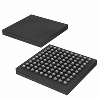
DS33ZH11+ Maxim Integrated Products, DS33ZH11+ Datasheet - Page 38

DS33ZH11+
Manufacturer Part Number
DS33ZH11+
Description
IC MAPPER ETHERNET 100CSBGA
Manufacturer
Maxim Integrated Products
Datasheet
1.DS33Z11.pdf
(172 pages)
Specifications of DS33ZH11+
Applications
Data Transport
Interface
Serial
Voltage - Supply
1.8V, 2.5V, 3.3V
Package / Case
100-LBGA
Mounting Type
Surface Mount
Lead Free Status / RoHS Status
Lead free / RoHS Compliant
- Current page: 38 of 172
- Download datasheet (2Mb)
DS33Z11 Ethernet Mapper
8.9 Serial Interface
The Serial (WAN) interface supports time-division multiplexed, serial data input and output up to 52 Mbps. The
Serial interface receives and transmits encapsulated Ethernet packets. The Serial Interface block consists of the
physical serial port and HDLC / X.86 engine. The physical interface consists of a Transmit Data, Transmit Clock,
Transmit Enable, Receive Data, Receive Clock, and Receive Enable. The WAN serial port can operate with a
gapped clock, and can be connected to a framer, electrical LIU, optical transceiver, or T/E-Carrier transceiver for
transmission to the WAN. The WAN interface can be connected to the Dallas Semiconductor/Maxim T1/E1/J1
framers, LIUs, and SCTs such as the DS26401, DS21348, and DS2155. The WAN interface can also be
connected to the Dallas Semiconductor/Maxim T3/E3/STS-1 framers, LIUs, and SCTs such as the DS3144 or
DS3154 to provide T3, E3, and STS1 connectivity.
8.10 Connections and Queues
The multiport devices in this product family provide bidirectional cross-connections between the multiple Ethernet
ports and Serial ports when operating in software mode. A single connection is preserved in this single-port
device to provide software compatibility with multi-port devices. The connection will have an associated transmit
and receive queue. Note that the terms “Transmit Queue” and “Receive Queue” are with respect to the Ethernet
Interface. The Receive queue is for data arriving from Ethernet interface to be transmitted to the WAN interface.
The Transmit queue is for data arriving from the WAN to be transmitted to the Ethernet interface. Hence the
transmit and receive direction terminology is the same as is used for the Ethernet MAC port.
The user can define the connection and the size of the transmit and receive queues. The size is adjustable in
units of 32(by 2048 byte) packets. The external SDRAM can hold up to 8192 packets of data. The user must
ensure that all the connection queues do no exceed this limit. The user also must ensure that the transmit and
receive queues do not overlap each other. Unidirectional connections are not supported.
When the user changes the queue sizes, the connection must be torn down and re-established. When a
connection is disconnected all transmit and receive queues associated with the connection are flushed and a “1’
is sourced towards the Serial transmit and the HDLC receiver. The clocks to the HDLC are sourced a “0.”
The user can also program High and Low watermarks. If the queue size grows past the High watermark, an
interrupt is generated if enabled. The registers of relevance are described in
Table
8-3. The AR.TQSC1 size
provides the size of the transmit queue for the connection. The High Watermark will set a latched status bit. The
latched status bit will clear when the register is read. The status bit is indicated by LI.TQCTLS.TQHTS. Interrupts
can be enabled on the latched bit events by LI.TQTIE. A latched status bit (LI.TQCTLS.TQLTS) is also set when
the queue crosses a low watermark.
The Receive Queue functions in a similar manner. Note that the user must ensure that sizes and watermarks are
set in accordance with the configuration speed of the Ethernet and Serial interfaces. The DS33Z11 does not
provide error indication if the user creates a connection and queue that overwrites data for another connection
queue. The user must take care in setting the queue sizes and watermarks. The registers of relevance are
AR.RQSC1and SU.QCRLS. Queue size should never be set to 0.
38 of 172
Related parts for DS33ZH11+
Image
Part Number
Description
Manufacturer
Datasheet
Request
R

Part Number:
Description:
MAX7528KCWPMaxim Integrated Products [CMOS Dual 8-Bit Buffered Multiplying DACs]
Manufacturer:
Maxim Integrated Products
Datasheet:

Part Number:
Description:
Single +5V, fully integrated, 1.25Gbps laser diode driver.
Manufacturer:
Maxim Integrated Products
Datasheet:

Part Number:
Description:
Single +5V, fully integrated, 155Mbps laser diode driver.
Manufacturer:
Maxim Integrated Products
Datasheet:

Part Number:
Description:
VRD11/VRD10, K8 Rev F 2/3/4-Phase PWM Controllers with Integrated Dual MOSFET Drivers
Manufacturer:
Maxim Integrated Products
Datasheet:

Part Number:
Description:
Highly Integrated Level 2 SMBus Battery Chargers
Manufacturer:
Maxim Integrated Products
Datasheet:

Part Number:
Description:
Current Monitor and Accumulator with Integrated Sense Resistor; ; Temperature Range: -40°C to +85°C
Manufacturer:
Maxim Integrated Products

Part Number:
Description:
TSSOP 14/A�/RS-485 Transceivers with Integrated 100O/120O Termination Resis
Manufacturer:
Maxim Integrated Products

Part Number:
Description:
TSSOP 14/A�/RS-485 Transceivers with Integrated 100O/120O Termination Resis
Manufacturer:
Maxim Integrated Products

Part Number:
Description:
QFN 16/A�/AC-DC and DC-DC Peak-Current-Mode Converters with Integrated Step
Manufacturer:
Maxim Integrated Products

Part Number:
Description:
TDFN/A/65V, 1A, 600KHZ, SYNCHRONOUS STEP-DOWN REGULATOR WITH INTEGRATED SWI
Manufacturer:
Maxim Integrated Products

Part Number:
Description:
Integrated Temperature Controller f
Manufacturer:
Maxim Integrated Products

Part Number:
Description:
SOT23-6/I�/45MHz to 650MHz, Integrated IF VCOs with Differential Output
Manufacturer:
Maxim Integrated Products

Part Number:
Description:
SOT23-6/I�/45MHz to 650MHz, Integrated IF VCOs with Differential Output
Manufacturer:
Maxim Integrated Products

Part Number:
Description:
EVALUATION KIT/2.4GHZ TO 2.5GHZ 802.11G/B RF TRANSCEIVER WITH INTEGRATED PA
Manufacturer:
Maxim Integrated Products

Part Number:
Description:
QFN/E/DUAL PCIE/SATA HIGH SPEED SWITCH WITH INTEGRATED BIAS RESISTOR
Manufacturer:
Maxim Integrated Products
Datasheet:


