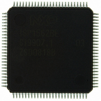
ISP1562BEGE ST-Ericsson Inc, ISP1562BEGE Datasheet - Page 54

ISP1562BEGE
Manufacturer Part Number
ISP1562BEGE
Description
IC USB PCI HOST CTRLR 100-LQFP
Manufacturer
ST-Ericsson Inc
Datasheet
1.ISP1562BEGE.pdf
(94 pages)
Specifications of ISP1562BEGE
Applications
USB Host/Function Processor
Interface
EHCI Interface
Voltage - Supply
3 V ~ 3.6 V
Package / Case
100-LQFP
Mounting Type
Surface Mount
Lead Free Status / RoHS Status
Lead free / RoHS Compliant
Other names
568-3157
ISP1562BE
ISP1562BE
Available stocks
Company
Part Number
Manufacturer
Quantity
Price
NXP Semiconductors
Table 81.
Address: Content of the base address register + 4Ch
Table 82.
Address: Content of the base address register + 4Ch
Table 83.
Address: Content of the base address register + 50h
ISP1562_2
Product data sheet
Bit
Symbol
Reset
Access
Bit
Symbol
Reset
Access
Bit
Symbol
Reset
Access
Bit
Symbol
Reset
Access
Bit
31 to 16
15 to 0
Bit
Symbol
Reset
Access
HcRhDescriptorB - Host Controller Root Hub Descriptor B register bit allocation
HcRhDescriptorB - Host Controller Root Hub Descriptor B register bit description
Symbol
PPCM
[15:0]
DR[15:0]
HcRhStatus - Host Controller Root Hub Status register bit allocation
11.1.21 HcRhStatus register
CRWE
R/W
R/W
R/W
R/W
R/W
31
23
15
31
0
0
0
7
0
0
Description
Port Power Control Mask: Each bit indicates whether a port is affected by a global power control
command when Power Switching Mode is set. When set, only the power state of the port is affected
by per-port power control (Set/Clear Port Power). When cleared, the port is controlled by the global
power switch (Set/Clear Global Power). If the device is configured to global switching mode (Power
Switching Mode = 0), this field is not valid.
Bit 0 — Reserved
Bit 1 — Ganged-power mask on port 1
Bit 2 — Ganged-power mask on port 2
Device Removable: Each bit is dedicated to a port of the root hub. When cleared, the attached
device is removable. When set, the attached device is not removable.
Bit 0 — Reserved
Bit 1 — Device attached to port 1
Bit 2 — Device attached to port 2
This register is divided into two parts. The lower word of a DWORD represents the Hub
Status field, and the upper word represents the Hub Status Change field. Reserved bits
must always be written as logic 0.
R/W
R/W
R/W
R/W
R/W
30
22
14
30
0
0
0
6
0
0
R/W
R/W
R/W
R/W
R/W
29
21
13
29
0
0
0
5
0
0
Rev. 02 — 1 March 2007
R/W
R/W
R/W
R/W
R/W
28
20
12
28
0
0
0
4
0
0
PPCM[15:8]
Table 83
PPCM[7:0]
DR[15:8]
DR[7:0]
reserved
shows the bit allocation of the register.
R/W
R/W
R/W
R/W
27
19
11
27
R
0
0
0
3
0
0
[1]
R/W
R/W
R/W
R/W
R/W
26
18
10
26
0
0
0
2
0
0
HS USB PCI Host Controller
R/W
R/W
R/W
R/W
R/W
25
17
25
0
1
9
0
1
0
0
© NXP B.V. 2007. All rights reserved.
ISP1562
R/W
R/W
R/W
R/W
R/W
24
16
24
0
0
8
0
0
0
0
53 of 93


