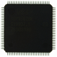
ISP1562BEGE ST-Ericsson Inc, ISP1562BEGE Datasheet - Page 68

ISP1562BEGE
Manufacturer Part Number
ISP1562BEGE
Description
IC USB PCI HOST CTRLR 100-LQFP
Manufacturer
ST-Ericsson Inc
Datasheet
1.ISP1562BEGE.pdf
(94 pages)
Specifications of ISP1562BEGE
Applications
USB Host/Function Processor
Interface
EHCI Interface
Voltage - Supply
3 V ~ 3.6 V
Package / Case
100-LQFP
Mounting Type
Surface Mount
Lead Free Status / RoHS Status
Lead free / RoHS Compliant
Other names
568-3157
ISP1562BE
ISP1562BE
Available stocks
Company
Part Number
Manufacturer
Quantity
Price
NXP Semiconductors
[1]
Table 100. FRINDEX - Frame Index register bit description
Address: Content of the base address register + 2Ch
ISP1562_2
Product data sheet
Bit
Symbol
Reset
Access
Bit
Symbol
Reset
Access
Bit
Symbol
Reset
Access
Bit
31 to 14
13 to 0
The reserved bits should always be written with the reset value.
Symbol
reserved
FRINDEX [13:0]
11.3.5 PERIODICLISTBASE register
R/W
R/W
R/W
23
15
0
0
7
0
reserved
Table 101. N based value of FLS[1:0]
The Periodic Frame List Base Address (PERIODLISTBASE) register contains the
beginning address of the periodic frame list in the system memory. If the Host Controller is
in 64-bit mode, as indicated by logic 1 in 64AC (bit 0 of the HCCPARAMS register), the
most significant 32 bits of every control data structure address comes from the
CTRLDSSEGMENT register. For details on the CTRLDSSEGMENT register, refer to
Enhanced Host Controller Interface Specification for Universal Serial Bus Rev. 1.0 . The
system software loads this register before starting the schedule execution by the Host
Controller. The memory structure referenced by this physical memory pointer is assumed
as 4 kB aligned. The contents of this register are combined with the FRINDEX register to
enable the Host Controller to step through the periodic frame list in sequence.
The bit allocation is given in
FLS[1:0]
00b
01b
10b
11b
[1]
R/W
R/W
R/W
22
14
Description
-
Frame Index: Bits in this register are used for the frame number in the SOF packet and as
the index into the frame list. The value in this register increments at the end of each time
frame. For example, microframe. The bits used for the frame number in the SOF token are
taken from bits 13 to 3 of this register. Bits N to 3 are used for the frame list current index.
This means that each location of the frame list is accessed eight times, frames or
microframes, before moving to the next index.
Table 101
register).
0
0
6
0
illustrates values of N based on the value of FLS[1:0] (bits 3 to 2 in the USBCMD
R/W
R/W
R/W
21
13
0
0
5
0
Rev. 02 — 1 March 2007
Table
Number elements
1024
512
256
reserved
R/W
R/W
R/W
20
12
0
0
4
0
FRINDEX[7:0]
102.
reserved
[1]
R/W
R/W
R/W
19
11
FRINDEX[13:8]
0
0
3
0
R/W
R/W
R/W
18
10
0
0
2
0
HS USB PCI Host Controller
N
12
11
10
-
R/W
R/W
R/W
17
0
9
0
1
0
© NXP B.V. 2007. All rights reserved.
ISP1562
R/W
R/W
R/W
16
0
8
0
0
0
67 of 93


