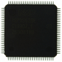
ISP1562BEGE ST-Ericsson Inc, ISP1562BEGE Datasheet - Page 66

ISP1562BEGE
Manufacturer Part Number
ISP1562BEGE
Description
IC USB PCI HOST CTRLR 100-LQFP
Manufacturer
ST-Ericsson Inc
Datasheet
1.ISP1562BEGE.pdf
(94 pages)
Specifications of ISP1562BEGE
Applications
USB Host/Function Processor
Interface
EHCI Interface
Voltage - Supply
3 V ~ 3.6 V
Package / Case
100-LQFP
Mounting Type
Surface Mount
Lead Free Status / RoHS Status
Lead free / RoHS Compliant
Other names
568-3157
ISP1562BE
ISP1562BE
Available stocks
Company
Part Number
Manufacturer
Quantity
Price
NXP Semiconductors
Table 96.
Address: Content of the base address register + 24h
Table 97.
Address: Content of the base address register + 28h
ISP1562_2
Product data sheet
Bit
3
2
1
0
Bit
Symbol
Reset
Access
Bit
Symbol
Reset
Access
Bit
Symbol
Reset
Access
USBSTS - USB Status register bit description
Symbol
FLR
PCD
USBERR
INT
USBINT
USBINTR - USB Interrupt Enable register bit allocation
11.3.3 USBINTR register
R/W
R/W
R/W
31
23
15
0
0
0
Description
Frame List Rollover: The Host Controller sets this bit to logic 1 when the frame list index rolls over
from its maximum value to zero. The exact value at which the rollover occurs depends on the frame
list size. For example, if the frame list size, as programmed in FLS (bits 3 to 2) of the USBCMD
register, is 1024, the Frame Index register rolls over every time bit 13 of the FRINDEX register
toggles. Similarly, if the size is 512, the Host Controller sets this bit to logic 1 every time bit 12 of the
FRINDEX register toggles.
Port Change Detect: The Host Controller sets this bit to logic 1 when any port, where PO (bit 13 of
PORTSC) is cleared, changes to logic 1, or FPR (bit 6 of PORTSC) changes to logic 1 as a result
of a J-K transition detected on a suspended port. This bit is allowed to be maintained in the
auxiliary power well. Alternatively, it is also acceptable that, on a D3-to-D0 transition of the EHCI
Host Controller device, this bit is loaded with the logical OR of all the PORTSC change bits,
including force port resume, overcurrent change, enable or disable change, and connect status
change.
USB Error Interrupt: The Host Controller sets this bit when an error condition occurs because of
completing a USB transaction. For example, error counter underflow. If the Transfer Descriptor (TD)
on which the error interrupt occurred also had its IOC bit set, both this bit and the USBINT bit are
set. For details, refer to Enhanced Host Controller Interface Specification for Universal Serial Bus
Rev. 1.0 .
USB Interrupt: The Host Controller sets this bit on completing a USB transaction, which results in
the retirement of a TD that had its IOC bit set. The Host Controller also sets this bit when a short
packet is detected, that is, the actual number of bytes received was less than the expected number
of bytes. For details, refer to Enhanced Host Controller Interface Specification for Universal Serial
Bus Rev. 1.0 .
The USB Interrupt Enable (USBINTR) register enables and disables reporting of the
corresponding interrupt to the software. When a bit is set and the corresponding interrupt
is active, an interrupt is generated to the host. Interrupt sources that are disabled in this
register still appear in USBSTS to allow the software to poll for events. The USBSTS
register bit allocation is given in
R/W
R/W
R/W
30
22
14
0
0
0
R/W
R/W
R/W
29
21
13
0
0
0
Rev. 02 — 1 March 2007
R/W
R/W
R/W
Table
28
20
12
…continued
0
0
0
reserved
reserved
reserved
97.
[1]
[1]
[1]
R/W
R/W
R/W
27
19
11
0
0
0
R/W
R/W
R/W
26
18
10
0
0
0
HS USB PCI Host Controller
R/W
R/W
R/W
25
17
0
0
9
0
© NXP B.V. 2007. All rights reserved.
ISP1562
R/W
R/W
R/W
24
16
0
0
8
0
65 of 93


