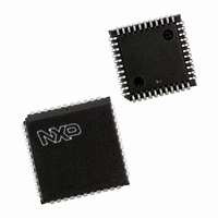
SC16C2552BIA44,529 NXP Semiconductors, SC16C2552BIA44,529 Datasheet - Page 11

SC16C2552BIA44,529
Manufacturer Part Number
SC16C2552BIA44,529
Description
IC UART DUAL W/FIFO 44-PLCC
Manufacturer
NXP Semiconductors
Type
Dual UART with 16-byte FIFOsr
Datasheet
1.SC16C2552BIA44529.pdf
(38 pages)
Specifications of SC16C2552BIA44,529
Number Of Channels
2, DUART
Package / Case
44-LCC (J-Lead)
Features
2 Channels
Fifo's
16 Byte
Voltage - Supply
2.5V, 3.3V, 5V
With Irda Encoder/decoder
Yes
With False Start Bit Detection
Yes
With Modem Control
Yes
With Cmos
Yes
Mounting Type
Surface Mount
Data Rate
5 Mbps
Supply Voltage (max)
5.5 V
Supply Voltage (min)
2.25 V
Supply Current
4.5 mA
Maximum Operating Temperature
+ 85 C
Minimum Operating Temperature
- 40 C
Mounting Style
SMD/SMT
Operating Supply Voltage
2.5 V or 3.3 V or 5 V
Lead Free Status / RoHS Status
Lead free / RoHS Compliant
Lead Free Status / RoHS Status
Lead free / RoHS Compliant, Lead free / RoHS Compliant
Other names
568-3646-5
935274408529
SC16C2552BIA44-S
935274408529
SC16C2552BIA44-S
Available stocks
Company
Part Number
Manufacturer
Quantity
Price
Company:
Part Number:
SC16C2552BIA44,529
Manufacturer:
NXP Semiconductors
Quantity:
10 000
NXP Semiconductors
7. Register descriptions
Table 6.
[1]
[2]
[3]
SC16C2552B_3
Product data sheet
A2
General register set
0
0
0
0
0
0
1
1
1
1
Special register set
0
0
0
The value shown represents the register’s initialized hexadecimal value; X = not applicable.
The ‘General register set’ registers are accessible only when CS is a logic 0 and LCR[7] is logic 0.
The Baud rate register and AFR register sets are accessible only when CS is a logic 0 and LCR[7] is a logic 1.
Set A is accessible when CHSEL is a logic 1, and Set B is accessible when CHSEL is a logic 0.
A1
0
0
0
1
1
1
0
0
1
1
0
0
1
A0
0
0
1
0
0
1
0
1
0
1
0
1
0
SC16C2552B internal registers
Register Default
RHR
THR
IER
FCR
ISR
LCR
MCR
LSR
MSR
SPR
DLL
DLM
AFR
[3]
[2]
Table 6
assigned bit functions are further defined in
XX
XX
00
00
01
00
00
60
X0
FF
XX
XX
00
details the assigned bit functions for the SC16C2552B internal registers. The
[1]
Bit 7
bit 7
bit 7
0
RCVR
trigger
(MSB)
FIFOs
enabled
divisor
latch
enable
0
FIFO
data
error
CD
bit 7
bit 7
bit 15
bit 7
5 V, 3.3 V and 2.5 V dual UART, 5 Mbit/s (max.), with 16-byte FIFOs
Rev. 03 — 12 February 2009
Bit 6
bit 6
bit 6
0
RCVR
trigger
(LSB)
FIFOs
enabled
set break set parity even
0
THR and
TSR
empty
RI
bit 6
bit 6
bit 14
bit 6
Bit 5
bit 5
bit 5
0
0
0
0
THR
empty
DSR
bit 5
bit 5
bit 13
bit 5
Bit 4
bit 4
bit 4
0
0
0
parity
loopback OP2
break
interrupt
CTS
bit 4
bit 4
bit 12
bit 4
Section 7.1
Bit 3
bit 3
bit 3
modem
status
interrupt
DMA
mode
select
INT
priority
bit 2
parity
enable
output
control
framing
error
bit 3
bit 3
bit 11
bit 3
CD
through
SC16C2552B
Bit 2
bit 2
bit 2
receive
line
status
interrupt
XMIT
FIFO
reset
INT
priority
bit 1
stop bits word
OP1
parity
error
bit 2
bit 2
bit 10
bit 2
RI
Section
© NXP B.V. 2009. All rights reserved.
Bit 1
bit 1
bit 1
transmit
holding
register
interrupt
RCVR
FIFO
reset
INT
priority
bit 0
length
bit 1
RTS
overrun
error
bit 1
bit 1
bit 9
bit 1
7.11.
DSR
Bit 0
bit 0
bit 0
receive
holding
register
FIFOs
enable
INT
status
word
length
bit 0
DTR
receive
data
ready
bit 0
bit 0
bit 8
bit 0
CTS
11 of 38


