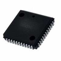
IS82C50A-5 Intersil, IS82C50A-5 Datasheet - Page 10

IS82C50A-5
Manufacturer Part Number
IS82C50A-5
Description
IC PERIPH UART/BRG 10MHZ 44-PLCC
Manufacturer
Intersil
Datasheet
1.CS82C50A-5Z.pdf
(25 pages)
Specifications of IS82C50A-5
Features
Single Chip UART/BRG
Number Of Channels
1, UART
Protocol
RS232C
Voltage - Supply
4.5 V ~ 5.5 V
With Parallel Port
Yes
With False Start Bit Detection
Yes
With Modem Control
Yes
With Cmos
Yes
Mounting Type
Surface Mount
Package / Case
44-LCC (J-Lead)
Lead Free Status / RoHS Status
Contains lead / RoHS non-compliant
Available stocks
Company
Part Number
Manufacturer
Quantity
Price
Company:
Part Number:
IS82C50A-5
Manufacturer:
TEMIC
Quantity:
12 388
Part Number:
IS82C50A-5
Manufacturer:
INTERSIL
Quantity:
20 000
MCR(3): When MCR(3) is set high, the OUT2 output is
forced low. When MCR(3) is reset low, the OUT2 output is
forced high. OUT2 is an user designated output.
MCR(4): MCR(4) provides a local loopback feature for
diagnostic testing of the 62C50A. When MCR(4) is set high,
Serial Output (SOUT) is set to the marking (logic 1) state,
and the receiver data input Serial Input (SIN) is
disconnected. The output of the Transmitter Shift Register is
looped back into the Receiver Shift Register input. The four
modem control inputs (CTS, DSR, DC, and RI) are
disconnected. The four modem control outputs (DTR, RTS,
OUT1 and OUT2) are internally connected to the four
modem control inputs. The modem control output pins are
MODEM STATUS REGISTER (MSR)
The MSR provides the CPU with status of the modem input
lines from the modem or peripheral device. The MSR allows
the CPU to read the modem signal inputs by accessing the
data bus interface of the 82C50A. In addition to the current
status information, four bits of the MSR indicate whether the
modem inputs have changed since the last reading of the
MSR. The delta status bits are set high when a control input
from the modem changes state, and reset low when the
CPU reads the MSR.
The modem input lines are CTS (pin 36), DSR (pin 37), RI
(pin 39), and DCD (pin 38). MSR(4) - MSR(7) are status
indications of these lines. The status indications follow the
status of the input lines. If the modem status interrupt in the
Interrupt Enable Register is enabled (IER(3)), a change of
state in a modem input signals will be reflected by the
modem status bits in the lIR register, and an interrupt
(lNTRPT) is generated. The MSR is a priority 4 interrupt. The
contents of the Modem Status Register are described below:
Note that the state (high or low) of the status bits are
inverted versions of the actual input pins.
MCR
7
MCR
6
10
MCR
5
MCR
4
MCR
3
MODEM CONTROL REGISTER (MCR)
MCR
2
MCR
1
82C50A
MCR
0
Data Terminal
Ready
Request to
Send
Out 1
Out 2
Loop
These Bits are Permanently Set to a Logic 0.
forced to their inactive state (high). In the diagnostic mode,
data transmitted is immediately received. This allows the
processor to verify the transmit and receive data paths of the
82C50A.
In the diagnostic mode, the receiver and transmitter
interrupts are fully operational. The modem control interrupts
are also operational, but the interrupt sources are now the
lower four bits of the MCR instead of the four modem control
inputs. The interrupts are still controlled by the Interrupt
Enable Register.
MCR(5) - MCR(7): These bits are permanently set to logic 0.
MSR(0) Delta Clear to Send (DCTS): DCTS indicates that
the CTS input (Pin-36) to the 82C50A has changed state
since the last time it was read by the CPU.
MSR(1) Delta Data Set Ready (DDSR): DDSR indicates
that the DSR input (Pin-37) to the 62C50A has changed
state since the last time it was read by the CPU.
MSR(2) Trailing Edge of Ring Indicator (TERI): TERI
indicates that the RI input (Pin-39) to the 82C50A has
Changed state from Low to High since the last time it was
read by the CPU. High to Low transitions on RI do not
activate TERI.
MSR BIT
MSR (1)
MSR (2)
MSR (0)
MSR (3)
MSR (4)
MSR (5)
MSR (6)
MSR (7)
0 = DTR Output High (Inactive)
1 = DTR Output Low (Active)
0 = RTS Output High (Inactive)
1 = RTS Output Low (Active)
0 = OUT 1 Output High (Inactive)
1 = OUT 1 Output Low (Active)
0 = OUT 2 Output High (Inactive)
1 = OUT 2 Output Low (Active)
0 = Loop Disabled
1 = Loop Enabled
MNEMONIC
DDSR
DDCD
MSR BITS 0 THRU 7
DCTS
TERI
DCD
DSR
CTS
RI
Delta Data Set Ready
Trailing Edge of Ring Indicator
Delta Clear To Send
Delta Data Carrier Detect
Clear To Send
Data Set Ready
Ring Indicator
Data Carrier Detect
DESCRIPTION
August 24, 2006
FN2958.5


