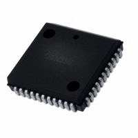
IS82C50A-5 Intersil, IS82C50A-5 Datasheet - Page 9

IS82C50A-5
Manufacturer Part Number
IS82C50A-5
Description
IC PERIPH UART/BRG 10MHZ 44-PLCC
Manufacturer
Intersil
Datasheet
1.CS82C50A-5Z.pdf
(25 pages)
Specifications of IS82C50A-5
Features
Single Chip UART/BRG
Number Of Channels
1, UART
Protocol
RS232C
Voltage - Supply
4.5 V ~ 5.5 V
With Parallel Port
Yes
With False Start Bit Detection
Yes
With Modem Control
Yes
With Cmos
Yes
Mounting Type
Surface Mount
Package / Case
44-LCC (J-Lead)
Lead Free Status / RoHS Status
Contains lead / RoHS non-compliant
Available stocks
Company
Part Number
Manufacturer
Quantity
Price
Company:
Part Number:
IS82C50A-5
Manufacturer:
TEMIC
Quantity:
12 388
Part Number:
IS82C50A-5
Manufacturer:
INTERSIL
Quantity:
20 000
The contents of the Line Status Register are indicated in the
above table and are described below.
LSR(0) Data Ready (DR): Data Ready is set high when an
incoming character has been received and transferred into
the Receiver Buffer Register. LSR(0) is reset low by a CPU
read of the data in the Receiver Buffer Register.
LSR(1) Overrun Error (OE): Overrun Error indicates that
data in the Receiver Buffer Register was not read by the
CPU before the next character was transferred into the
Receiver Buffer Register, overwriting the previous character.
The OE indicator is reset whenever the CPU reads the
contents of the Line Status Register.
LSR(2) Parity Error (PE): Parity Error indicates that the
received data character does not have the correct even or
odd parity, as selected by the Even Parity Select bit (LCR
(4)). The PE bit is set high upon detection of a parity error,
and is reset low when the CPU reads the contents of the
LSR.
LSR(3) Framing Error (FE): Framing Error indicates that
the received character did not have a valid stop bit. LSR(3)
is set high when the stop bit following the last data bit or
parity bit is detected as a zero bit (spacing level). The FE
indicator is reset low when the CPU reads the contents of
the LSR.
LSR(4) Break Interrupt (BI): Break Interrupt is set high
when the received data input is held in the spacing (logic 0)
state for longer than a full word transmission time (start bit +
data bits + parity + stop bits). The B indicator is reset when
the CPU reads the contents of the Line Status Register.
LSR(1) - LSR(4) are the error conditions that produce a
Receiver Line Status interrupt (priority 1 interrupt in the
Interrupt Identification Register (IIR)) when any of the
conditions are detected. This interrupt is enabled by setting
lER (2) = 1 in the Interrupt Enable Register.
LSR(5) Transmitter Holding Register Empty
(THRE): THRE indicates that the 82C50A is ready to accept
a new character for transmission. The THRE bit is set high
when a character is transferred from the Transmitter Holding
LSR
LSR
LSR
LSR
LSR
LSR
LSR
LSR
(0) Data Ready (DR)
(1) Overrun Error (OE)
(2) Parity Error (PE)
(3) Framing Error (FE)
(4) Break Interrupt (BI)
(5) Transmitter Holding
(6) Transmitter Empty (TEMT)
(7) Not Used
Register Empty (THRE)
LSR BITS 0 THRU 7
9
LOGIC 1
Ready
Empty
Empty
Break
Error
Error
Error
Not Ready
Not Empty
Not Empty
No Break
LOGIC 0
No Error
No Error
No Error
82C50A
Register into the Transmitter Shift Register. LSR(5) is reset
low by the loading of the Transmitter Holding Register by the
CPU. LSR(5) is not reset by a CPU read of the LSR.
When the THRE interrupt is enabled (IER(1) = 1), THRE
causes a priority 3 interrupt in the lIR. If THRE is the interrupt
source indicated in IIR, lNTRPT is cleared by a read of the
IIR.
LSR(6) Transmitter Empty (TEMT): TEMT is set high
when the Transmitter Holding Register (THR) and the
Transmitter Shift Register (TSR) are both empty. LSR(6) is
reset low when a character is loaded into the THR and
remains low until the character is transferred out of SOUT.
TEMT is not reset low by a CPU read of the LSR.
LSR(7): This bit is permanently set to logic 0.
MODEM CONTROL REGISTER (MCR)
The MCR controls the interface with the modem or data set
as described below. The MCR can be written and read. The
RTS, DTR, OUT1 and OUT2 outputs are directly controlled
by their control bits in this register. A high input asserts a
low (true) at the output pins.
MCR(0): When MCR(0) is set high, the DTR output is forced
low. When MCR(0) is reset low, the DTR output is forced
high. The DTR output of the 82C50A may be input into an
ElA inverting line driver as the 1488 to obtain the proper
polarity input at the modem or data set.
MCR(1): When MCR(1) is set high, the RTS output is forced
low. When MCR(1) is reset low, the RTS output is forced
high. The RTS output of the 82C50A may be input into an
ElA inverting line driver as the 1488 to obtain the proper
polarity input at the modem or data set.
MCR(2): When MCR(2) is set high, the OUT1 output is
forced low. When MCR(2) is reset low, the OUT1 output is
forced high. OUT1 is an user designated output.
MCR
MCR
MCR
MCR
MCR
MCR
MCR
MCR
(0) Data Terminal Ready
(1) Request to Send
(2) OUT1
(3) OUT2
(4) LOOP
(5) 0
(6) 0
(7) 0
(DTR)
(RTS)
MCR BITS 0 THRU 7
Output Low
Output Low
Output Low
Output Low
MCR BIT
LOGIC 1
Enabled
LOOP
OUT1
OUT2
DTR
RTS
Output High
Output High
Output High
Output High
MCR BIT
LOGIC 0
Disabled
August 24, 2006
LOOP
OUT1
OUT2
RTS
DTR
FN2958.5


