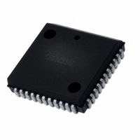
IS82C50A-5 Intersil, IS82C50A-5 Datasheet - Page 15

IS82C50A-5
Manufacturer Part Number
IS82C50A-5
Description
IC PERIPH UART/BRG 10MHZ 44-PLCC
Manufacturer
Intersil
Datasheet
1.CS82C50A-5Z.pdf
(25 pages)
Specifications of IS82C50A-5
Features
Single Chip UART/BRG
Number Of Channels
1, UART
Protocol
RS232C
Voltage - Supply
4.5 V ~ 5.5 V
With Parallel Port
Yes
With False Start Bit Detection
Yes
With Modem Control
Yes
With Cmos
Yes
Mounting Type
Surface Mount
Package / Case
44-LCC (J-Lead)
Lead Free Status / RoHS Status
Contains lead / RoHS non-compliant
Available stocks
Company
Part Number
Manufacturer
Quantity
Price
Company:
Part Number:
IS82C50A-5
Manufacturer:
TEMIC
Quantity:
12 388
Part Number:
IS82C50A-5
Manufacturer:
INTERSIL
Quantity:
20 000
Reset
After powerup, the 82C50A Master Reset Schmitt trigger
input (MR) should be held high for TMRW ns to reset the
82C50A circuits to an idle mode until initialization. A high on
MR causes the following:
1. Initializes the transmitter and receiver internal clock
2. Clears the Line Status Register (LSR), except for
DESIRED
Interrupt Enable Register
Interrupt Identification Register
Line Control Register
MODEM Control Register
Line Status Register
MODEM Status Register
SOUT
lntrpt (RCVR Errs)
lntrpt (RCVR Data Ready)
lntrpt (THRE)
lntrpt (Modem Status Changes)
Out2
RTS
DTR
Out1
BAUD
19200
38400
RATE
134.5
1200
1800
2000
2400
3600
4800
7200
9600
counters.
Transmitter Shift Register Empty (TE MT) and Transmit
Holding Register Empty (THRE), which are set. The
Modem Control Register (MCR) is also cleared. All of the
discrete lines, memory elements and miscellaneous logic
110
150
300
600
50
75
TABLE 5. BAUD RATES USING 2.4576MHz CRYSTAL
REGISTER/SIGNAL
DIVISOR USED TO
16 x CLOCK
GENERATE
3072
2048
1396
1024
1142
512
256
128
85
77
64
43
32
21
16
8
4
15
DIFFERENCE BETWEEN
DESIRED AND ACTUAL
PERCENT ERROR
0.0007
0.026
0.392
0.260
0.775
1.587
Read lIR/Write THR/MR
TABLE 7. 82C50A RESET OPERATIONS
-
-
-
-
-
-
-
-
-
-
-
RESET CONTROL
Read MSR/MR
Read RBR/MR
Read LSR/MR
Master Reset
Master Reset
Master Reset
Master Reset
Master Reset
Master Reset
Master Reset
Master Reset
Master Reset
Master Reset
Master Reset
82C50A
Following removal of the reset condition (MR low), the
82C50A remains in the idle mode until programmed.
A hardware reset of the 82C50A sets the THRE and TEMT
status bit in the LSR. When interrupts are subsequently
enabled, an interrupt occurs due to THRE.
A summary of the effect of a Master Reset on the 82C50A is
given in Table 7.
DESIRED
BAUD
19200
38400
RATE
134.5
1200
1800
2000
2400
3600
4800
7200
9600
associated with these register bits are also cleared or
turned off. Divisor Latches, Receiver Buffer Register,
Transmitter Buffer Register are not effected.
150
300
600
110
50
75
TABLE 6. BAUD RATES USING 3.072MHz CRYSTAL
All Bits Low (0-3 forced and 4-7 permanent)
Bit 0 is High, Bits 1 and 2 Low Bits 3-7 are Permanently Low
All Bits Low
All Bits Low
All Bits Low, Except Bits 5 and 6 are High
Bit 0-3 Low Bits 4-7 Input Signal
High
Low
Low
Low
Low
High
High
High
High
DIVISOR USED TO
16 x CLOCK
GENERATE
3840
2560
1745
1428
1280
640
320
160
107
96
80
53
40
27
20
10
5
RESET
DIFFERENCE BETWEEN
DESIRED AND ACTUAL
PERCENT ERROR
0.026
0.034
0.312
0.628
1.23
-
-
-
-
-
-
-
-
-
-
-
-
August 24, 2006
FN2958.5


