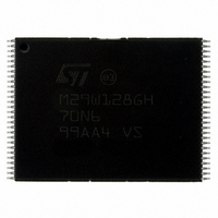
M29W128GH70N6E NUMONYX, M29W128GH70N6E Datasheet - Page 27

M29W128GH70N6E
Manufacturer Part Number
M29W128GH70N6E
Description
IC FLASH 128MBIT 70NS 56TSOP
Manufacturer
NUMONYX
Series
Axcell™r
Datasheet
1.M29W128GH70N6E.pdf
(94 pages)
Specifications of M29W128GH70N6E
Format - Memory
FLASH
Memory Type
FLASH
Memory Size
128M (16Mx8, 8Mx16)
Speed
70ns
Interface
Parallel
Voltage - Supply
2.7 V ~ 3.6 V
Operating Temperature
-40°C ~ 85°C
Package / Case
56-TSOP
Package
56TSOP
Cell Type
NOR
Density
128 Mb
Architecture
Sectored
Block Organization
Symmetrical
Typical Operating Supply Voltage
3|3.3 V
Sector Size
128KByte x 128
Timing Type
Asynchronous
Interface Type
Parallel
Lead Free Status / RoHS Status
Lead free / RoHS Compliant
Available stocks
Company
Part Number
Manufacturer
Quantity
Price
Company:
Part Number:
M29W128GH70N6E
Manufacturer:
Numonyx
Quantity:
17 280
Company:
Part Number:
M29W128GH70N6E
Manufacturer:
MICRON
Quantity:
595
Company:
Part Number:
M29W128GH70N6E
Manufacturer:
MICRON45
Quantity:
556
Part Number:
M29W128GH70N6E
Manufacturer:
ST
Quantity:
20 000
6
6.1
6.1.1
6.1.2
Command interface
All bus write operations to the memory are interpreted by the command interface.
Commands consist of one or more sequential bus write operations. Failure to observe a
valid sequence of bus write operations will result in the memory returning to read mode. The
long command sequences are imposed to maximize data security.
The address used for the commands changes depending on whether the memory is in 16-
bit or 8-bit mode.
Standard commands
See either
summary of the standard commands.
Read/Reset command
The device is in read mode after reset or after power-up.
The Read/Reset command returns the memory to read mode. It also resets the errors in the
status register. Either one or three bus write operations can be used to issue the
Read/Reset command.
The Read/Reset command can be issued, between bus write cycles before the start of a
program or erase operation, to return the device to read mode. If the Read/Reset command
is issued during the timeout of a block erase operation, the memory will take up to 10 µs to
abort. During the abort period no valid data can be read from the memory.
The Read/Reset command will not abort an erase operation when issued while in erase
suspend.
Auto Select command
The Auto Select command puts the device in auto select mode, when using the in-system
method (see
read the manufacturer code, the device code, the protection status of each block (block
protection status) and the extended memory block protection indicator.
Three consecutive bus write operations are required to issue the Auto Select command.
Once the Auto Select command is issued bus read operations to specific addresses output
the manufacturer code, the device code, the extended memory block protection indicator
and a block protection status (see
Table
or CFI Query command is issued.
7,
Table
Table
Section 3.7: Auto select
8, and
10, or
Table
Table
9). The memory remains in auto select mode until a Read/Reset
11, depending on the configuration that is being used, for a
Table 10
mode). When in auto select mode, the system can
and
Table 11
in conjunction with
Table
6,
27/94


