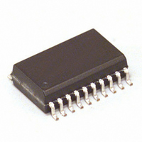
MCZ33883EG Freescale Semiconductor, MCZ33883EG Datasheet - Page 15

MCZ33883EG
Manufacturer Part Number
MCZ33883EG
Description
IC PRE-DRIVER FULL BRIDGE 20SOIC
Manufacturer
Freescale Semiconductor
Type
High Side/Low Sider
Datasheet
1.MCZ33883EGR2.pdf
(21 pages)
Specifications of MCZ33883EG
Configuration
H Bridge
Input Type
Non-Inverting
Delay Time
200ns
Current - Peak
2A
Number Of Configurations
1
Number Of Outputs
4
Voltage - Supply
5.5 V ~ 55 V
Operating Temperature
-40°C ~ 125°C
Mounting Type
Surface Mount
Package / Case
20-SOIC (7.5mm Width)
Rise Time
180 ns
Fall Time
180 ns
Supply Voltage (min)
5.5 V
Supply Current
2.2 mA
Maximum Power Dissipation
1250 mW
Maximum Operating Temperature
+ 125 C
Mounting Style
SMD/SMT
Bridge Type
H Bridge
Minimum Operating Temperature
- 40 C
Number Of Drivers
4
Lead Free Status / RoHS Status
Lead free / RoHS Compliant
High Side Voltage - Max (bootstrap)
-
Lead Free Status / Rohs Status
Lead free / RoHS Compliant
Available stocks
Company
Part Number
Manufacturer
Quantity
Price
Part Number:
MCZ33883EG
Manufacturer:
FREESCALE
Quantity:
20 000
Company:
Part Number:
MCZ33883EGR2
Manufacturer:
FREESCALE
Quantity:
1 490
Part Number:
MCZ33883EGR2
Manufacturer:
FREESCALE
Quantity:
20 000
C
and the working switching frequency.
diagrams that depict the influence of C
average voltage level. The diagrams represent two different
frequencies for two power MOSFETs, MTP60N06HD and
MPT36N06V.
value is. Moreover, for the same C
switching frequency increases, the average V
decreases. For most of the applications, a typical value of
33 nF is recommended.
Analog Integrated Circuit Device Data
Freescale Semiconductor
CP
C
The smaller the C
21.5
20.5
19.5
18.5
CP
20.5
19.5
18.5
21
20
19
21
20
19
18
5
choice depends on power MOSFET characteristics
5
MTP60N06HD (Q
MTP60N06HD (Q
Figure 10. V
25
MTP60N06HD (Q
25
MTP36N06V (Q
CP
C
C
45
Ccp (nF)
45
Ccp (nF)
CP
CP
value is, the smaller the V
(nF)
(nF)
CP_OUT
65
65
g
g
=50nC)
= 50 nC)
g
g
Versus C
CP
= 50 nC)
= 40 nC)
85
Figure 10
85
value, when the
CP
value on V
CP
CP_OUT
contains two
CP_OUT
100 kHz
20 kHz
100 kHz
20 kHz
20KhZ
100 KhZ
CP_OUT
level
rage V
V
Average
V
I
C
voltage waveforms. f
CP_OUT
voltage decreases. This decrease can be calculated
according to the C
Where Q
C
MOSFET turn-on. V
TYPICAL VALUES OF CAPACITORS
recommended for a well-performing charge pump:
These values give a typical 100 mV voltage ripple on
V
V
CP_OUT
CP_OUT
I
Cp_out
CP_OUT
Cp_out
CP_OUT
LR_OUT
Cp_out
Figure 11
As shown above, at high-side MOSFET turn-on V
C
In most working cases the following typical values are
C
Figure 11. Simplified C
LR_OUT
CP
= 33 nF, C
g
and V
Oscillator
in high
state
Oscillator
in High
State Oscillator
f=330kHz
f = 330 kHz
is power MOSFET gate charge.
provides peak current needed by the low-side
depicts the simplified C
Oscillator
in low
state
in Low
State
LR_OUT
∆V
Peak Current
CP_OUT
CP_OUT
∆V
LR_OUT
PWM
CP_OUT
LR_OUT
Current
with Q
Peak
Waveforms
is the working switching frequency.
= 470 nF, and C
value as follows:
FUNCTIONAL DEVICE OPERATION
decrease is as follows:
CP_OUT
=
g
=
= 50 nC.
C
C
CP_OUT
LR_OUT
Q
Current and Voltage
Q
CP_OUT
g
∆V
∆
g
OPERATIONAL MODES
V
Ccp
CP_OUT
_
out
High Side Turn On
f
High Side
turn on
f
PWM
LR_OUT
PWM
current and
= 470 nF
CP_OUT
33883
15


