ISL62870HRUZ-T Intersil, ISL62870HRUZ-T Datasheet - Page 9
ISL62870HRUZ-T
Manufacturer Part Number
ISL62870HRUZ-T
Description
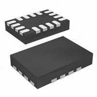
IC CTRLR VREG PWM DC/DC 16-TQFN
Manufacturer
Intersil
Datasheet
1.ISL62870HRUZ-T.pdf
(16 pages)
Specifications of ISL62870HRUZ-T
Pwm Type
Controller
Number Of Outputs
1
Frequency - Max
330kHz
Duty Cycle
100%
Voltage - Supply
3.3 V ~ 25 V
Buck
Yes
Boost
No
Flyback
No
Inverting
No
Doubler
No
Divider
No
Cuk
No
Isolated
No
Operating Temperature
-10°C ~ 100°C
Package / Case
16-UTQFN (16-µTQFN)
Frequency-max
330kHz
Lead Free Status / RoHS Status
Lead free / RoHS Compliant
Available stocks
Company
Part Number
Manufacturer
Quantity
Price
Company:

Part Number:
ISL62870HRUZ-T
Manufacturer:
M/A-COM
Quantity:
45
Part Number:
ISL62870HRUZ-T
Manufacturer:
INTERSIL
Quantity:
20 000


output voltage (V
V
The negative slope of V
Where g
A window voltage V
amplifier output voltage V
which the ripple voltage V
V
V
is the lower threshold voltage and V
voltage. Figure 6 shows PWM pulses being generated as V
traverses the V
switching frequency is proportional to the slew rates of the
positive and negative slopes of V
proportional to the voltage between V
Synchronous Rectification
A standard DC/DC buck regulator uses a free-wheeling
diode to maintain uninterrupted current conduction through
the output inductor when the high-side MOSFET switches off
for the balance of the PWM switching cycle. Low conversion
efficiency as a result of the conduction loss of the diode
makes this an unattractive option for all but the lowest
current applications. Efficiency is dramatically improved
when the free-wheeling diode is replaced with a MOSFET
that is turned on whenever the high-side MOSFET is turned
off. This modification to the standard DC/DC buck regulator
is referred to as synchronous rectification, the topology
implemented by the ISL62870 controller.
Diode Emulation
The polarity of the output inductor current is defined as positive
when conducting away from the phase node, and defined as
V
V
RPOS
R
W
W
RNEG
RIPPLE CAPACITOR VOLTAGE C
FIGURE 6. MODULATOR WAVEFORMS DURING LOAD
can be written as Equation 10:
is controlled internally by the IC. The V
signals feed into a window comparator in which V
=
=
m
(
g
g
is the gain of the transconductance amplifier.
m
m
⋅
)
TRANSIENT
V
⋅
W
(
OUT
V
OUT
and V
IN
W
–
⁄
C
) at the VO pin. The positive slope of
V
is referenced with respect to the error
R
OUT
ERROR AMPLIFIER VOLTAGE V
COMP
R
COMP
R
can be written as Equation 11:
) C
is compared. The amplitude of
⁄
R
9
thresholds. The PWM
R
, creating an envelope into
R;
W
it is inversely
W
WINDOW VOLTAGE V
is the higher threshold
and V
PWM
R,
V
COMP.
COMP,
COMP
(EQ. 10)
(EQ. 11)
COMP
and
W
ISL62870
R
negative when conducting towards the phase node. The DC
component of the inductor current is positive, but the AC
component known as the ripple current, can be either positive
or negative. Should the sum of the AC and DC components of
the inductor current remain positive for the entire switching
period, the converter is in continuous-conduction-mode (CCM.)
However, if the inductor current becomes negative or zero, the
converter is in discontinuous-conduction-mode (DCM.)
Unlike the standard DC/DC buck regulator, the synchronous
rectifier can sink current from the output filter inductor during
DCM, reducing the light-load efficiency with unnecessary
conduction loss as the low-side MOSFET sinks the inductor
current. The ISL62870 controller avoids the DCM conduction
loss by making the low-side MOSFET emulate the current
blocking behavior of a diode. This smart-diode operation
called diode-emulation-mode (DEM) is triggered when the
negative inductor current produces a positive voltage drop
across the
consecutive PWM cycles while the LGATE pin is high. The
converter will exit DEM on the next PWM pulse after
detecting a negative voltage across the
side MOSFET.
It is characteristic of the R
switching frequency to decrease while in DCM, increasing
efficiency by reducing unnecessary gate-driver switching
losses. The extent of the frequency reduction is proportional
to the reduction of load current. Upon entering DEM, the
PWM frequency is forced to fall approximately 30% by
forcing a similar increase of the window voltage V
measure is taken to prevent oscillating between modes at
the boundary between CCM and DCM. The 30% increase of
V
frequency to jump back to the nominal CCM value.
Power-On Reset
The IC is disabled until the voltage at the VCC pin has
increased above the rising power-on reset (POR) threshold
voltage V
when the voltage
POR threshold voltage V
noise filter of approximately 1µs.
VIN and PVCC Voltage Sequence
Prior to pulling EN above the V
voltage, the following criteria must be met:
Start-Up Timing
Once VCC has ramped above V
be enabled by pulling the EN pin voltage above the input high
threshold V
SREF pin begins slewing to the designated VID set-point. The
1. V
2. V
W
reset voltage V
application.
is removed upon exit of DEM, forcing the PWM switching
PVCC
VIN
VCC_THR
must be 3.3V or the minimum required by the
ENTHR
r
DS(ON)
is at least equivalent to the VCC rising power-on
at the
. Approximately 20µs later, the voltage at the
of the low-side MOSFET for eight
VCC_THR
. The controller will become disabled
VCC pin decreases below the falling
VCC_THF
3
architecture for the PWM
ENTHR
VCC_THR
. The POR detector has a
rising threshold
r
, the controller can
DS(ON)
of the low-
August 14, 2008
W
. This
FN6708.0
Related parts for ISL62870HRUZ-T
Image
Part Number
Description
Manufacturer
Datasheet
Request
R

Part Number:
Description:
PWM DC/DC Voltage Regulator Controller
Manufacturer:
Intersil Corporation
Datasheet:
Part Number:
Description:
Intersil Corporation [CMOS Serial Controller Interface]
Manufacturer:
Intersil Corporation
Datasheet:
Part Number:
Description:
Manufacturer:
Intersil Corporation
Datasheet:
Part Number:
Description:
357-036-542-201 CARDEDGE 36POS DL .156 BLK LOPRO
Manufacturer:
Intersil Corporation
Datasheet:
Part Number:
Description:
1024-Word x 4-Bit LSI Static RAM
Manufacturer:
Intersil Corporation
Datasheet:
Part Number:
Description:
General Purpose NPN Transistor Arrays FN341.4
Manufacturer:
Intersil Corporation
Datasheet:
Part Number:
Description:
CMOS 16-Bit Microprocessor
Manufacturer:
Intersil Corporation
Datasheet:
Part Number:
Description:
Manufacturer:
Intersil Corporation
Datasheet:
Part Number:
Description:
Manufacturer:
Intersil Corporation
Datasheet:
Part Number:
Description:
Manufacturer:
Intersil Corporation
Datasheet:
Part Number:
Description:
Manufacturer:
Intersil Corporation
Datasheet:
Part Number:
Description:
CMOS 6-Bit Latch and Decoder Memory Interfaces
Manufacturer:
Intersil Corporation
Datasheet:
Part Number:
Description:
CA3046General Purpose NPN Transistor Arrays
Manufacturer:
Intersil Corporation
Datasheet:
Part Number:
Description:
Manufacturer:
Intersil Corporation
Datasheet:
Part Number:
Description:
TR909 DLC/FLC SLIC with Low Power Standby
Manufacturer:
Intersil Corporation
Datasheet: