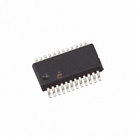
ISL6442IA Intersil, ISL6442IA Datasheet - Page 10

ISL6442IA
Manufacturer Part Number
ISL6442IA
Description
IC PWM BUCK VM 24QSOP
Manufacturer
Intersil
Datasheet
1.ISL6442IAZ-TK.pdf
(16 pages)
Specifications of ISL6442IA
Pwm Type
Voltage Mode
Number Of Outputs
3
Frequency - Max
2.85MHz
Duty Cycle
100%
Voltage - Supply
4.5 V ~ 24 V
Buck
Yes
Boost
No
Flyback
No
Inverting
No
Doubler
No
Divider
No
Cuk
No
Isolated
No
Operating Temperature
-40°C ~ 85°C
Package / Case
24-QSOP
Frequency-max
2.85MHz
Lead Free Status / RoHS Status
Contains lead / RoHS non-compliant
Available stocks
Company
Part Number
Manufacturer
Quantity
Price
Company:
Part Number:
ISL6442IAZ
Manufacturer:
Intersil
Quantity:
97
Company:
Part Number:
ISL6442IAZ
Manufacturer:
ST
Quantity:
6 267
Part Number:
ISL6442IAZ
Manufacturer:
INTERSIL
Quantity:
20 000
Part Number:
ISL6442IAZ-T
Manufacturer:
INTERSIL
Quantity:
20 000
Company:
Part Number:
ISL6442IAZ-TK
Manufacturer:
Intersil
Quantity:
6 000
Output Regulation
Figure 11 shows the generic feedback resistor circuit for any
of the three V
reference. All three use a 0.6V internal reference (check the
“Electrical Specifications” Table on page 4 for the exact
reference value at 24V). The R
the R
V
and their accuracy directly affect the regulator tolerance.
Use Equation 5 to choose the resistor values. R
the compensation network for the switchers, and should be
selected to be compatible; 1kΩ to 5kΩ is a good starting
value. Find FB from the “Electrical Specifications” Table on
page 5 (for the right condition), plug in the desired value for
V
The maximum duty cycle of the ISL6442 approaches 100%
at low frequency, but falls off at higher frequency; see the
“Electrical Specifications” Table on page 5. In addition, there
is a minimum UGATE pulse width, in order to properly sense
overcurrent. The two switchers are 180° out of phase.
The linear output voltage is restricted to approximately a 1V to
4V range. VIN3 should be equal or less than VCC (in order to
be sure that LCDR can turn off the PNP). Note that the linear
output is off until the rising POR trips; it does not have a
FB
R
OUT
OUT
LOW
=
4.0
3.5
3.0
2.5
2.0
1.5
1.0
0.5
0.0
LOW
, and solve for R
V
must be greater than 0.6V and 2 resistors are needed,
0
=
OUT
----------------------------- -
V
FIGURE 10. FREQUENCY vs RT RESISTOR
FB R
V
to GND; the common point goes to the FB pin.
OUT
OUT
⋅
5
-----------------------------------
R
FIGURE 11. OUTPUT REGULATION
⋅
OUT
UP
–
UP
R
FB
R
LOW
+
’s; the V
UP
10
R
LOW
LOW
15
OUT
.
10
R
FB
RT (kΩ)
LOW
UP
is divided down to equal the
20
is connected to the V
0.6V
25
EA
30
COMP
UP
35
is part of
(EQ. 4)
(EQ. 5)
OUT
40
;
ISL6442
soft-start ramp, and it does NOT shut off, unless VCC goes
back below the falling POR trip point. It is suggested that using
one of the switcher outputs as the input to the linear allows it to
be ramped and enabled/disabled with that switcher.
Protection Mechanisms
OCP - (Function independent for both PWM). The overcurrent
function protects the PWM Converter from a shorted output by
using the upper MOSFET’s ON-resistance, r
the current. This method enhances the converter’s efficiency
and reduces cost by eliminating a current sensing resistor. The
overcurrent function cycles the soft-start function in a hiccup
mode to provide fault protection. A resistor connected to the
drain of the upper MOSFET and OCSET pin programs the
overcurrent trip level. The PHASE node voltage will be
compared against the voltage on the OCSET pin, while the
upper MOSFET is on. A current (typically 110µA) is pulled from
the OCSET pin to establish the OCSET voltage. If PHASE is
lower than OCSET while the upper MOSFET is on then an
overcurrent condition is detected for that clock cycle. The upper
gate pulse is immediately terminated, and a counter is
incremented. If an overcurrent condition is detected for 32
consecutive clock cycles, and the circuit is not in soft-start, the
ISL6442 enters into the soft-start hiccup mode. During hiccup,
the external capacitor on the SS/EN pin is discharged, then
released and a soft-start cycle is initiated. During soft-start,
pulse termination current limiting is enabled, but the 32-cycle
hiccup counter is held in reset until soft-start is completed.
Figure 12 shows an example of the hiccup mode. As the
SS2/EN2 is pulled below the enable trip point, VOUT2 shuts
off, and the voltage goes to GND, at which time the output
current goes to zero. As SS2/EN2 rises above the enable
trip point, the output tries to turn on, the current spikes up,
and then is held constant (by the pulse-termination current
limiting); the output voltage rises, but not up to the desired
value. When the SS2/EN2 ramp reaches ~3V, the cycle
repeats, and can continue indefinitely. If the short-circuit is
removed, the output will ramp up with the next soft-start, and
normal operation will resume. VOUT1 and SS1/EN1 will
independently function the same way.
GND>
GND>
0A>
FIGURE 12. OVERCURRENT PROTECTION
SS2/EN2 (1V/DIV)
DS(ON)
VOUT2 (2V/DIV)
I
OUT2
October 31, 2008
to monitor
(2A/DIV)
FN9204.2


