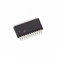
ISL6442IA Intersil, ISL6442IA Datasheet - Page 11

ISL6442IA
Manufacturer Part Number
ISL6442IA
Description
IC PWM BUCK VM 24QSOP
Manufacturer
Intersil
Datasheet
1.ISL6442IAZ-TK.pdf
(16 pages)
Specifications of ISL6442IA
Pwm Type
Voltage Mode
Number Of Outputs
3
Frequency - Max
2.85MHz
Duty Cycle
100%
Voltage - Supply
4.5 V ~ 24 V
Buck
Yes
Boost
No
Flyback
No
Inverting
No
Doubler
No
Divider
No
Cuk
No
Isolated
No
Operating Temperature
-40°C ~ 85°C
Package / Case
24-QSOP
Frequency-max
2.85MHz
Lead Free Status / RoHS Status
Contains lead / RoHS non-compliant
Available stocks
Company
Part Number
Manufacturer
Quantity
Price
Company:
Part Number:
ISL6442IAZ
Manufacturer:
Intersil
Quantity:
97
Company:
Part Number:
ISL6442IAZ
Manufacturer:
ST
Quantity:
6 267
Part Number:
ISL6442IAZ
Manufacturer:
INTERSIL
Quantity:
20 000
Part Number:
ISL6442IAZ-T
Manufacturer:
INTERSIL
Quantity:
20 000
Company:
Part Number:
ISL6442IAZ-TK
Manufacturer:
Intersil
Quantity:
6 000
UVP - (Function independent for both PWM). If the voltage
on the FB pin falls to 82% (typical) of the reference voltage
for 8 consecutive PWM cycles, then the circuit enters into
soft-start hiccup mode. This mode is identical to the
overcurrent hiccup mode. The UVP comparator is separate
from the one sensing for PGOOD, which should have
already detected a problem, before the UVP trips.
OVP - (Function independent for both PWM). If voltage on
FB pin rises to 116% (typical) of the reference voltage, the
lower gate driver is turned on continuously (with diode
emulation enabled). If SS_DN (internal soft-start done
signal) is true (not in soft-start) and the overvoltage condition
continues for 32 consecutive PWM cycles, then that output
is latched off with the gate drivers three-stated. The
capacitor on the SS/EN pin will not be discharged. The
switcher will restart when the SS/EN pin is externally driven
below 1V, or if power is recycled to the chip, or when the
voltage on the FB pin falls to the 82% (typical) undervoltage
threshold - after 8 clock cycles the chip will enter soft-start
hiccup mode. The hiccup mode is identical to the
overcurrent hiccup mode. The OVP comparator is separate
from the one sensing for PGOOD, which should have
already detected a problem, before the OVP trips.
Application Guidelines
PWM Controller
DISCUSSION
The PWM must be compensated such that it achieves the
desired transient performance goals, stability, and DC
regulation requirements.
The first parameter that needs to be chosen is the switching
frequency, F
constraints and the frequency plan of the end equipment.
Smaller space requires higher frequency. This allows the
output inductor, input capacitor bank, and output capacitor
bank to be reduced in size and/or value. The power supply
must be designed such that the frequency and its distribution
over component tolerance, time and temperature causes
minimal interference in RF stages, IF stages, PLL loops,
mixers, etc.
INDUCTOR SELECTION
The output inductor is selected to meet the output voltage
ripple requirements and minimize the converter’s response
time to the load transient. The inductor value determines the
converter’s ripple current, and the ripple voltage is a function
of the ripple current. The ripple current and voltage are
approximated by the following equations, where ESR is the
output capacitance ESR value.
ΔI
=
V
------------------------------- -
IN
F
SW
- V
•
SW
OUT
L
. This decision is based on the overall size
•
V
--------------- -
V
OUT
IN
11
(EQ. 6)
ISL6442
Increasing the value of inductance reduces the ripple current
and voltage. However, the large inductance value reduces
the converter’s response time to a load transient (and
usually increases the DCR of the inductor, which decreases
the efficiency). Increasing the switching frequency (F
a given inductor also reduces the ripple current and voltage.
One of the parameters limiting the converter’s response to a
load transient is the time required to change the inductor
current. Given a sufficiently fast control loop design, the
ISL6442 will provide either 0% or 100% duty cycle in
response to a load transient. The response time is the time
required to slew the inductor current from an initial current
value to the transient current level. During this interval, the
difference between the inductor current and the transient
current level must be supplied by the output capacitor.
Minimizing the response time can minimize the output
capacitance required.
The response time to a transient is different for the
application of load and the removal of load. The following
equations give the approximate response time interval for
application and removal of a transient load:
where: I
response time to the application of load, and t
response time to the removal of load. With a +5V input
source, the worst case response time can be either at the
application or removal of load and dependent upon the
output voltage setting. Be sure to check both of these
equations at the minimum and maximum output levels for
the worst case response time.
Finally, check that the inductor I
the maximum output current (DC load plus ripple current).
OUTPUT CAPACITOR SELECTION
An output capacitor is required to filter the output and supply
the load transient current. The filtering requirements are a
function of the switching frequency and the ripple current.
The load transient requirements are a function of the slew
rate (di/dt) and the magnitude of the transient load current.
These requirements are generally met with a mix of
capacitors and careful layout.
Modern microprocessors produce transient load rates above
1A/ns. High frequency capacitors initially supply the transient
and slow the current load rate seen by the bulk capacitors.
The bulk filter capacitor values are generally determined by
the ESR (effective series resistance) and voltage rating
requirements rather than actual capacitance requirements.
t
ΔV
t
RISE
FALL
OUT
=
=
TRAN
= ΔI x ESR
L
-------------------------------------- -
L
-------------------------------------- -
OUT
V
OUT
IN
V
–
OUT
is the transient load current step, t
×
×
V
I
I
TRAN
OUT
TRAN
sat
rating is sufficiently above
FALL
RISE
October 31, 2008
is the
SW
(EQ. 7)
(EQ. 8)
(EQ. 9)
FN9204.2
is the
) for


