PBMCUSLK Freescale Semiconductor, PBMCUSLK Datasheet - Page 10
PBMCUSLK
Manufacturer Part Number
PBMCUSLK
Description
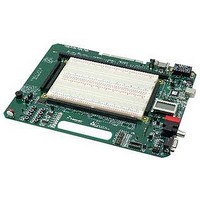
PROJECT BOARD FOR MCU
Manufacturer
Freescale Semiconductor
Datasheet
1.PBMCUSLK.pdf
(30 pages)
Specifications of PBMCUSLK
Module/board Type
Student Learning Kit
Silicon Manufacturer
Freescale
Core Architecture
HCS08, S12
Core Sub-architecture
HCS08, S12
Silicon Core Number
MC9S08, MC9S12
Silicon Family Name
S08QG, S12D
Rohs Compliant
Yes
For Use With/related Products
HC(S)12(X), HC(S)08, DSP, and ColdFire modules
Lead Free Status / RoHS Status
Lead free / RoHS Compliant


Input Selection
The PBMCUSLK sources power from the VIN barrel connector, the USB BDM, or connector
J1. The barrel connector is situated on the project board to prevent connection of an external
power supply while connected to the NI-ELVIS workstation. Two selection headers determine
the source of input power to the project board. These selection headers are situated to
prevent selecting 2 input power sources at the same time.
Selection headers PWR_SEL(JP1) and +5V_SEL (JP2)
input source to supply power to the project board. PWR_SEL selects either connector VIN or
connector J1 as an input source. +5V_SEL selects either the output of PWR_SEL(JP1) or the
USB BDM as an input source. The output of PWR_SEL connects directly to pin 3 of +5V_SEL.
The output of +5V_SEL drives the 5V rail and the input of the 3.3V regulator, VR2.
Figure 1: Input Power Select
Power input on the barrel connector is supplied by the included wall-plug transformer or a
desktop power supply. Input voltage on this connector should be between +8V and +12V.
Higher input voltages may cause excessive heating and force VR1 into thermal shutdown.
Power input from the USB connector is drawn from the USB bus. Care must be exercised not
to draw too much power when connected to the USB bus. USB2.0 specifications limit the total
current drain from the bus to less than 500mA. Exceeding this limit will cause the USB device
to disconnect and may damage the project board or host PC.
VDD Selection
The operating voltage level VDD supplies all on-board logic devices on the PBMCUSLK. An
option header allows the user to set VDD at either 5V or 3.3V.
When the project board is connected to a wall-plug transformer, voltage regulator VR1
provides the 5V rail and regulator VR2 provides the 3.3V rail. Regulator VR1 is rated for a
*
respectively.
10
For project boards labeled MCU Project Board -2 AXM-0368 Rev C these jumpers are labeled PSEL_A and PSEL_B
PWR_SEL
+5V_SEL
JP1
JP2
1
2
●
1
2
●
J1
VIN
USB
JP1
Selects J1 input source
Selects USB input
source to supply 5V rail
JP1
JP2
●
2
3
●
2
3
J1
VIN
USB
JP1
*
illustrated in figure 1 select which
Selects VIN input source
Selects JP1 input source to
supply 5V rail.
Freescale Semiconductor
Related parts for PBMCUSLK
Image
Part Number
Description
Manufacturer
Datasheet
Request
R

Part Number:
Description:
Manufacturer:
Freescale Semiconductor, Inc
Datasheet:
Part Number:
Description:
Manufacturer:
Freescale Semiconductor, Inc
Datasheet:
Part Number:
Description:
Manufacturer:
Freescale Semiconductor, Inc
Datasheet:
Part Number:
Description:
Manufacturer:
Freescale Semiconductor, Inc
Datasheet:
Part Number:
Description:
Manufacturer:
Freescale Semiconductor, Inc
Datasheet:
Part Number:
Description:
Manufacturer:
Freescale Semiconductor, Inc
Datasheet:
Part Number:
Description:
Manufacturer:
Freescale Semiconductor, Inc
Datasheet:
Part Number:
Description:
Manufacturer:
Freescale Semiconductor, Inc
Datasheet:
Part Number:
Description:
Manufacturer:
Freescale Semiconductor, Inc
Datasheet:
Part Number:
Description:
Manufacturer:
Freescale Semiconductor, Inc
Datasheet:
Part Number:
Description:
Manufacturer:
Freescale Semiconductor, Inc
Datasheet:
Part Number:
Description:
Manufacturer:
Freescale Semiconductor, Inc
Datasheet:
Part Number:
Description:
Manufacturer:
Freescale Semiconductor, Inc
Datasheet:
Part Number:
Description:
Manufacturer:
Freescale Semiconductor, Inc
Datasheet:
Part Number:
Description:
Manufacturer:
Freescale Semiconductor, Inc
Datasheet: