PBMCUSLK Freescale Semiconductor, PBMCUSLK Datasheet - Page 17
PBMCUSLK
Manufacturer Part Number
PBMCUSLK
Description
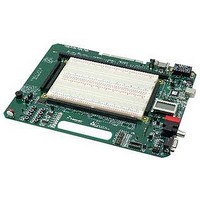
PROJECT BOARD FOR MCU
Manufacturer
Freescale Semiconductor
Datasheet
1.PBMCUSLK.pdf
(30 pages)
Specifications of PBMCUSLK
Module/board Type
Student Learning Kit
Silicon Manufacturer
Freescale
Core Architecture
HCS08, S12
Core Sub-architecture
HCS08, S12
Silicon Core Number
MC9S08, MC9S12
Silicon Family Name
S08QG, S12D
Rohs Compliant
Yes
For Use With/related Products
HC(S)12(X), HC(S)08, DSP, and ColdFire modules
Lead Free Status / RoHS Status
Lead free / RoHS Compliant


LCD Enable
The LCD_EN
general purpose I/O if needed. To use the SPI signals as general purpose I/O, simply remove
the shunts at this option header.
Figure 10: LCD_EN Option Header
Oscillator Socket
The PBMCUSLK provides a socket for an optional clock oscillator. The socket is configured to
accept either 8-pin or 14-pin canned clock oscillators. An AMPL
table 3 allows the use of 5V oscillators to drive 3.3V circuits. Removing the option jumper
routes the clock output through a simple voltage divider thereby reducing the output amplitude.
Installing the option jumper allows a 5V, peak, clock output. This output is routed to the signal
breakout header located adjacent to the breadboard.
Table 3: AMPL Option Header
Switches
The PBMCUSLK provides two types of switches for use as input devices. Eight normally open
push button switches
voltage level while in the inactive state.
PUSHBUTTON SWITCHES
Each push button switch is configured for active-low operation. When pressed (closed) the
associated signal line is pulled to GND through a 1 kΩ, current-limit resistor. A 10k ohm
resistor pulls each signal line to VDD when the switch is released (open). Each push-button
switch output is routed to the signal breakout header labeled “USER I/O PB[1..7]” located
adjacent to the breadboard.
MCU_PORT connector, see “Connected Features” section below for details.
*
†
Freescale Semiconductor
Not applicable for project boards labeled “MCU Project Board”
For project boards labeled “MCU Project Board -2 AXM-0368 Rev C” this jumper is labeled OSC_OPT.
Shunt
ON
OFF
LCD_EN
●
●
●
*
option header illustrated in figure 10 allows module SPI signals to be used as
●
●
●
Effect
Oscillator Output at Full Amplitude – 5V
Oscillator Output at Reduced Amplitude – 3.3V
MOSI
MISO
SCK
SPI signals connected to LCD
Port
Four push-button switches are connected directly to the
PP
LCD_EN
●
●
●
PP
●
●
●
MOSI
MISO
SCK
†
option jumper described in
SPI signals available as GPIO
17
Related parts for PBMCUSLK
Image
Part Number
Description
Manufacturer
Datasheet
Request
R

Part Number:
Description:
Manufacturer:
Freescale Semiconductor, Inc
Datasheet:
Part Number:
Description:
Manufacturer:
Freescale Semiconductor, Inc
Datasheet:
Part Number:
Description:
Manufacturer:
Freescale Semiconductor, Inc
Datasheet:
Part Number:
Description:
Manufacturer:
Freescale Semiconductor, Inc
Datasheet:
Part Number:
Description:
Manufacturer:
Freescale Semiconductor, Inc
Datasheet:
Part Number:
Description:
Manufacturer:
Freescale Semiconductor, Inc
Datasheet:
Part Number:
Description:
Manufacturer:
Freescale Semiconductor, Inc
Datasheet:
Part Number:
Description:
Manufacturer:
Freescale Semiconductor, Inc
Datasheet:
Part Number:
Description:
Manufacturer:
Freescale Semiconductor, Inc
Datasheet:
Part Number:
Description:
Manufacturer:
Freescale Semiconductor, Inc
Datasheet:
Part Number:
Description:
Manufacturer:
Freescale Semiconductor, Inc
Datasheet:
Part Number:
Description:
Manufacturer:
Freescale Semiconductor, Inc
Datasheet:
Part Number:
Description:
Manufacturer:
Freescale Semiconductor, Inc
Datasheet:
Part Number:
Description:
Manufacturer:
Freescale Semiconductor, Inc
Datasheet:
Part Number:
Description:
Manufacturer:
Freescale Semiconductor, Inc
Datasheet: