PBMCUSLK Freescale Semiconductor, PBMCUSLK Datasheet - Page 19
PBMCUSLK
Manufacturer Part Number
PBMCUSLK
Description
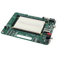
PROJECT BOARD FOR MCU
Manufacturer
Freescale Semiconductor
Datasheet
1.PBMCUSLK.pdf
(30 pages)
Specifications of PBMCUSLK
Module/board Type
Student Learning Kit
Silicon Manufacturer
Freescale
Core Architecture
HCS08, S12
Core Sub-architecture
HCS08, S12
Silicon Core Number
MC9S08, MC9S12
Silicon Family Name
S08QG, S12D
Rohs Compliant
Yes
For Use With/related Products
HC(S)12(X), HC(S)08, DSP, and ColdFire modules
Lead Free Status / RoHS Status
Lead free / RoHS Compliant


Potentiometer
The PBMCUSLK provides a single-turn, 5K ohm trim potentiometer for use in circuit
prototyping. Most commonly, the POT may be used to provide analog input signals to the
microcontroller. This signal is routed to the signal breakout header labeled “USER I/O POT”
located adjacent to the breadboard.
A bypass capacitor on the output provides minimal
smoothing on the POT signal.
The POT is configured as a Connected Feature. See Connected Features section below for
details.
Banana Jack
The PBMCUSLK provides two 4.0mm banana jacks for use as auxiliary I/O. These connectors
may be used for auxiliary signal input or for signal output to test equipment. The banana jacks
are color-coded, red, and black. The center conductor of each jack is routed to the User I/O
Signal Breakout connector labeled USER I/O BANANA [A..B] located adjacent to the
breadboard area.
BNC Jack
The PBMCUSLK provides one BNC jack for use as auxiliary I/O. This connector may be used
for auxiliary signal input or for signal output to test equipment. The center conductor (BNC+)
and shield (BNC-) are routed separately to the User I/O Signal Breakout connector labeled
USER I/O BNC[+/-] located adjacent to the breadboard area. For proper operation, both
signals must be connected. For most circuit configurations, BNC- should be connected to
GND.
Connected Features
To simplify circuit construction and emphasize software development, several user features
have been connected to the MCU_PORT through FET switches and jumpers.
The FET
switches are controlled by enable signals that are also routed to the MCU_PORT header. This
setup allows the user to electronically connect and disconnect each connected feature group.
A 6-position jumper (UFEA or JP10) allows the user to disconnect the enable signal if applying
the associated port to other uses.
Connected Features include a POT, 4 push-button
switches, and 4 LED’s. Each feature group function is more fully described elsewhere in this
User Guide.
Freescale Semiconductor
19
Related parts for PBMCUSLK
Image
Part Number
Description
Manufacturer
Datasheet
Request
R

Part Number:
Description:
Manufacturer:
Freescale Semiconductor, Inc
Datasheet:
Part Number:
Description:
Manufacturer:
Freescale Semiconductor, Inc
Datasheet:
Part Number:
Description:
Manufacturer:
Freescale Semiconductor, Inc
Datasheet:
Part Number:
Description:
Manufacturer:
Freescale Semiconductor, Inc
Datasheet:
Part Number:
Description:
Manufacturer:
Freescale Semiconductor, Inc
Datasheet:
Part Number:
Description:
Manufacturer:
Freescale Semiconductor, Inc
Datasheet:
Part Number:
Description:
Manufacturer:
Freescale Semiconductor, Inc
Datasheet:
Part Number:
Description:
Manufacturer:
Freescale Semiconductor, Inc
Datasheet:
Part Number:
Description:
Manufacturer:
Freescale Semiconductor, Inc
Datasheet:
Part Number:
Description:
Manufacturer:
Freescale Semiconductor, Inc
Datasheet:
Part Number:
Description:
Manufacturer:
Freescale Semiconductor, Inc
Datasheet:
Part Number:
Description:
Manufacturer:
Freescale Semiconductor, Inc
Datasheet:
Part Number:
Description:
Manufacturer:
Freescale Semiconductor, Inc
Datasheet:
Part Number:
Description:
Manufacturer:
Freescale Semiconductor, Inc
Datasheet:
Part Number:
Description:
Manufacturer:
Freescale Semiconductor, Inc
Datasheet: