PBMCUSLK Freescale Semiconductor, PBMCUSLK Datasheet - Page 6
PBMCUSLK
Manufacturer Part Number
PBMCUSLK
Description
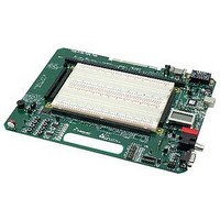
PROJECT BOARD FOR MCU
Manufacturer
Freescale Semiconductor
Datasheet
1.PBMCUSLK.pdf
(30 pages)
Specifications of PBMCUSLK
Module/board Type
Student Learning Kit
Silicon Manufacturer
Freescale
Core Architecture
HCS08, S12
Core Sub-architecture
HCS08, S12
Silicon Core Number
MC9S08, MC9S12
Silicon Family Name
S08QG, S12D
Rohs Compliant
Yes
For Use With/related Products
HC(S)12(X), HC(S)08, DSP, and ColdFire modules
Lead Free Status / RoHS Status
Lead free / RoHS Compliant


FEATURES
The PBMCUSLK is a full-featured prototyping platform intended for interfacing and
programming Freescale MCU development modules in an educational environment. A line of
HC(S)12(X), HC(S)08, DSP, and ColdFire modules plug directly into the project board. Other
MCU boards can be interfaced directly to the project board by ribbon cable. The PBMCUSLK
may also be used as an electronic circuit prototyping environment without MCU support. The
project board has been specifically designed for compatibility with the National Instruments
Educational Laboratory Virtual Instrumentation Suite (NI-ELVIS). An integrated USB BDM
POD has been provided to allow the user to program, erase, and debug supported Freescale
MCU modules. Features include:
•
•
•
•
•
•
•
•
•
•
•
•
6
Large, Replaceable, Solderless Breadboard Area
Integrated HC(S)12(X)/HCS08 Multilink BDM
•
•
•
60-pin MCU Interface Connector, break-out on both
ends of prototype area
PCI Style Card-Edge connector designed for use with
National Instrument’s NI-ELVIS platform
Signal Breakout arranged logically around
Breadboard Area
Power Input from included wall-plug transformer,
integrated USB-BDM, or from NI-ELVIS
workstation
On-board voltage regulators provide 4 different
voltage levels
•
•
•
•
•
•
User selectable voltage to on-board logic devices
•
2 Banana Connectors
1 BNC Connector
8-pin Keypad connector
1 Single-turn User Potentiometer
•
Allows debugging target processor via
background debug mode
Provides all necessary signals to target processor
USB port connection
5VDC @ 500mA
3.3VDC @ 500mA
+15VDC @ 50mA
–15VDC @ 50mA
NOTE: ± 15V is not available when powered
from USB-BDM
LED indicators for each voltage level
Option jumper to enable voltage output to MCU
Port Connector
Connected to MCU_PORT connector w/
separate enable
•
•
•
•
•
•
•
Specifications:
Module Size:
Power Input:
8-character x 2-line LCD panel
•
•
•
COM Port
•
•
•
•
Socket for Optional Crystal Oscillator
•
8 Active-High Green LED’s, Buffered, with enable
•
8 Active-Low Push Button Switches
•
8 Active-High DIP Switches,
1 External-drive Buzzer
•
•
Fixed and Variable Contrast
Selectable Chip Select
Option header to disconnect signal lines
9-pin DSUB connector
RS-232 Interface with option to isolate
transceiver
COM_SEL jumper selects configuration
between:
•
•
Access to COM signals at Signal Breakout
Connector
User selectable output amplitude - 5V or 3.3V
4 LED’s connected to MCU_PORT connector w/
separate enable
4 Push Button Switches connected to
MCU_PORT connector w/ separate enable
Connected to MCU_PORT connector w/
separate enable
Mounting hole placement allows the student to
carry the Project Board in a standard 3-Ring
binder.
RS-232 signals to transceiver
MON08 Interface Port
8.5” x 11”
+9V @ 1.2A typical
Freescale Semiconductor
Related parts for PBMCUSLK
Image
Part Number
Description
Manufacturer
Datasheet
Request
R

Part Number:
Description:
Manufacturer:
Freescale Semiconductor, Inc
Datasheet:
Part Number:
Description:
Manufacturer:
Freescale Semiconductor, Inc
Datasheet:
Part Number:
Description:
Manufacturer:
Freescale Semiconductor, Inc
Datasheet:
Part Number:
Description:
Manufacturer:
Freescale Semiconductor, Inc
Datasheet:
Part Number:
Description:
Manufacturer:
Freescale Semiconductor, Inc
Datasheet:
Part Number:
Description:
Manufacturer:
Freescale Semiconductor, Inc
Datasheet:
Part Number:
Description:
Manufacturer:
Freescale Semiconductor, Inc
Datasheet:
Part Number:
Description:
Manufacturer:
Freescale Semiconductor, Inc
Datasheet:
Part Number:
Description:
Manufacturer:
Freescale Semiconductor, Inc
Datasheet:
Part Number:
Description:
Manufacturer:
Freescale Semiconductor, Inc
Datasheet:
Part Number:
Description:
Manufacturer:
Freescale Semiconductor, Inc
Datasheet:
Part Number:
Description:
Manufacturer:
Freescale Semiconductor, Inc
Datasheet:
Part Number:
Description:
Manufacturer:
Freescale Semiconductor, Inc
Datasheet:
Part Number:
Description:
Manufacturer:
Freescale Semiconductor, Inc
Datasheet:
Part Number:
Description:
Manufacturer:
Freescale Semiconductor, Inc
Datasheet: