DM163029 Microchip Technology, DM163029 Datasheet - Page 12
DM163029
Manufacturer Part Number
DM163029
Description
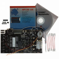
BOARD PICDEM FOR MECHATRONICS
Manufacturer
Microchip Technology
Specifications of DM163029
Main Purpose
Power Management, Motor Control
Embedded
*
Utilized Ic / Part
*
Primary Attributes
*
Secondary Attributes
*
Processor To Be Evaluated
PIC16F917
Interface Type
RS-232
Silicon Manufacturer
Microchip
Silicon Core Number
DM163029
Silicon Family Name
PICDEM
Kit Contents
PICDEM Mechatronics Board, MCU Samples, Software And Cables
Rohs Compliant
Yes
Lead Free Status / RoHS Status
Lead free / RoHS Compliant
Lead Free Status / RoHS Status
Lead free / RoHS Compliant, Lead free / RoHS Compliant
Available stocks
Company
Part Number
Manufacturer
Quantity
Price
Company:

Part Number:
DM163029
Manufacturer:
Microchip Technology
Quantity:
135
Company:
Part Number:
DM163029
Manufacturer:
MICROCHIP
Quantity:
12 000


PICDEM
1.3
DS51557C-page 8
QUICK START GUIDE
TM
The PICDEM Mechatronics Demo Board is programmed at the factory with a
demonstration program. The board must be configured as described in this chapter in
order to use the demonstration program. Once the board is configured and powered
up, the speed of the Brushed DC (BDC) motor on the board may be varied using the
potentiometer (POT1). The 8-bit hexadecimal interpretation of the position of POT1 is
displayed on the LCD.
Board Setup
Using the provided wire jumpers, screwdriver and shunts (2-pin black hard plastic
jumpers), configure the board as shown in Figure 1-1.
1. Attach the leads of the Brushed DC motor to Drive 1 and Drive 2 using the
2. Connect POT1 (on J4) to C1- (on J13) using a wire jumper.
3. Connect P1 (on J1) to RD7 (on J10) using a wire jumper.
4. Connect N2 (on J1) to RD2 (on J10) using a wire jumper.
5. Connect the right and center pins on JP8 using a shunt.
Board Power-Up
Supply power to the board in one of the following ways:
• Connect a 9-12 V
• Connect a 9-12 V
• Connect a 9 V
• Connect a 5 V
Demonstration Program
Press CLR FAULT (SW5), which is near the bottom right corner of the board. Turn
POT1 clockwise to increase the speed of the motor. Note that the number displayed on
the LCD increases as you turn the potentiometer clockwise.
Try experimenting with the other sensors on the board:
• Move the jumper wire on POT1 (J4) to Light (J4). Vary the intensity of light shining
• Move the jumper to TEMP (J4). Blow on the temperature sensor located on the
• Move the jumper back to POT1. Move the jumper from N2 (J1) to D0 (J14). Watch
Mechatronics Demo Board User’s Guide
terminals.
on the light sensor located near the top left corner of the board. Notice what
happens to the motor.
top left corner of the board. Note what happens to the number displayed on the
LCD.
what happens to the intensity of LED D0 as you turn the potentiometer.
Note:
screwdriver.
The power supply part number is AC162039 (see buy.microchip.com). Packaged
with the MPLAB ICD 2, the part number is DV164007.
DC
DC
DC
DC
battery to the battery connector.
(1.2 amp minimum) supply to TP2 or TP3.
(0.75 amp minimum) supply using J9 (see note below)
(0.75 amp minimum) supply to the P21 and P20 screw
© 2006 Microchip Technology Inc.
Related parts for DM163029
Image
Part Number
Description
Manufacturer
Datasheet
Request
R

Part Number:
Description:
Manufacturer:
Microchip Technology Inc.
Datasheet:
Part Number:
Description:
Manufacturer:
Microchip Technology Inc.
Datasheet:
Part Number:
Description:
Manufacturer:
Microchip Technology Inc.
Datasheet:
Part Number:
Description:
Manufacturer:
Microchip Technology Inc.
Datasheet:
Part Number:
Description:
Manufacturer:
Microchip Technology Inc.
Datasheet:
Part Number:
Description:
Manufacturer:
Microchip Technology Inc.
Datasheet:
Part Number:
Description:
Manufacturer:
Microchip Technology Inc.
Datasheet:
Part Number:
Description:
Manufacturer:
Microchip Technology Inc.
Datasheet: