DM163029 Microchip Technology, DM163029 Datasheet - Page 51
DM163029
Manufacturer Part Number
DM163029
Description
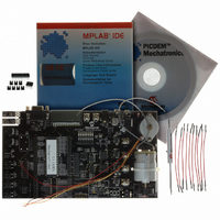
BOARD PICDEM FOR MECHATRONICS
Manufacturer
Microchip Technology
Specifications of DM163029
Main Purpose
Power Management, Motor Control
Embedded
*
Utilized Ic / Part
*
Primary Attributes
*
Secondary Attributes
*
Processor To Be Evaluated
PIC16F917
Interface Type
RS-232
Silicon Manufacturer
Microchip
Silicon Core Number
DM163029
Silicon Family Name
PICDEM
Kit Contents
PICDEM Mechatronics Board, MCU Samples, Software And Cables
Rohs Compliant
Yes
Lead Free Status / RoHS Status
Lead free / RoHS Compliant
Lead Free Status / RoHS Status
Lead free / RoHS Compliant, Lead free / RoHS Compliant
Available stocks
Company
Part Number
Manufacturer
Quantity
Price
Company:

Part Number:
DM163029
Manufacturer:
Microchip Technology
Quantity:
135
Company:
Part Number:
DM163029
Manufacturer:
MICROCHIP
Quantity:
12 000


3.1
3.2
© 2006 Microchip Technology Inc.
INTRODUCTION
COMMON PROBLEMS
This chapter describes common problems associated with using the PICDEM™
Mechatronics and steps on how to resolve them.
3.2.1
The board must be powered by one of the following:
• A 9-12 V
• A 9-12 V
• A 9 V
• A 5 V
Supplying less than 9 V
to function properly causing V
3.2.2
There must be a two-pin shunt present on JP8 connecting the middle pin to +5 V
9-12 V
the drive stage is disabled. Press the CLR FAULT button (SW5) to enable the drive
stage.
3.2.3
Verify that the motor is not drawing over 1.2 amps. Check the voltage at CURRENT
SENSE (J15) before the FAULT LED turns on again. Voltage is equal to the current at
J15, therefore, if the voltage is 1.2V or greater, the drive is drawing too much current or
possibly shorted.
Verify the motor is being driven properly. The N-channel and P-channel MOSFETs on
any given Drive (DRIVE 1, DRIVE 2, etc.) should not be turned on simultaneously. (See
note).
J2 connects the MOSFET control lines for DRIVE 1 and DRIVE 2 and J3 connects the
control lines for DRIVE 3 and DRIVE 4. If shunts are present on J2 and J3, verify that
they are connected intentionally and not from a previous design.
Note:
DC
DC
DC
Chapter 3. Troubleshooting
. This is the supply reference for the drive stage. If the FAULT LED (D8) is on,
V
No Voltage On Drive Stage
FAULT LED Stays On Or Continues To Trip When SW5 Is
Pressed
DC
DC
battery
power source at TP2 and TP3
Hardware is in place to ensure the N-channel and P-channel MOSFETs on
a given Drive are not turned on at the same time. However, if you are
switching the N-channel MOSFET rapidly, it is possible for both MOSFETs
to be on at the same time.
DD
source at the screw terminals (P20 and P21)
source at J9
Is Below 5V
DC
at J9 or the screw terminals will not allow the regulator (U3)
DEMO BOARD USER’S GUIDE
DD
PICDEM
to be below 5 V
TM
DC
.
MECHATRONICS
DS51557C-page 47
DC
or
Related parts for DM163029
Image
Part Number
Description
Manufacturer
Datasheet
Request
R

Part Number:
Description:
Manufacturer:
Microchip Technology Inc.
Datasheet:
Part Number:
Description:
Manufacturer:
Microchip Technology Inc.
Datasheet:
Part Number:
Description:
Manufacturer:
Microchip Technology Inc.
Datasheet:
Part Number:
Description:
Manufacturer:
Microchip Technology Inc.
Datasheet:
Part Number:
Description:
Manufacturer:
Microchip Technology Inc.
Datasheet:
Part Number:
Description:
Manufacturer:
Microchip Technology Inc.
Datasheet:
Part Number:
Description:
Manufacturer:
Microchip Technology Inc.
Datasheet:
Part Number:
Description:
Manufacturer:
Microchip Technology Inc.
Datasheet: