DM163029 Microchip Technology, DM163029 Datasheet - Page 33
DM163029
Manufacturer Part Number
DM163029
Description
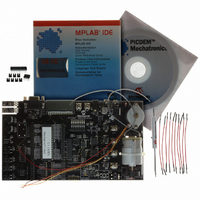
BOARD PICDEM FOR MECHATRONICS
Manufacturer
Microchip Technology
Specifications of DM163029
Main Purpose
Power Management, Motor Control
Embedded
*
Utilized Ic / Part
*
Primary Attributes
*
Secondary Attributes
*
Processor To Be Evaluated
PIC16F917
Interface Type
RS-232
Silicon Manufacturer
Microchip
Silicon Core Number
DM163029
Silicon Family Name
PICDEM
Kit Contents
PICDEM Mechatronics Board, MCU Samples, Software And Cables
Rohs Compliant
Yes
Lead Free Status / RoHS Status
Lead free / RoHS Compliant
Lead Free Status / RoHS Status
Lead free / RoHS Compliant, Lead free / RoHS Compliant
Available stocks
Company
Part Number
Manufacturer
Quantity
Price
Company:

Part Number:
DM163029
Manufacturer:
Microchip Technology
Quantity:
135
Company:
Part Number:
DM163029
Manufacturer:
MICROCHIP
Quantity:
12 000


© 2006 Microchip Technology Inc.
2.3.5
Motor control is required in many mechatronic applications ranging from power
windows to washing machine cycle control. This project will demonstrate speed control
of a Brushed DC motor. Brushed DC motor control is simple as the commutation, or
sequencing of power to the various windings, is automatically performed by the motor’s
brushes. In this project, the Capture Compare PWM (CCP) module will be used in
PWM mode to generate a Brushed DC motor drive. Timer1 will measure speed
feedback from the optical interrupter on the board. The optical interrupter circuit
generates a high signal when light passes through the slots in the encoder disk. By
measuring the time between pulses, the speed of the motor can be determined. A
real-life application example includes precision speed control of a fan or hard disk
drive.
Objectives
1. Configure the CCP module to generate a PWM signal.
2. Use a PWM signal to vary the speed of a Brushed DC motor.
3. Configure Timer1 to use the optical interrupter as its clock source.
Applicable Technical Documents
Brushed DC Motor Fundamentals Application Note, AN905 (DS00905)
Low-Cost Bidirectional Brushed DC Motor Control Using the PIC16F684 Application
Note, AN893 (DS00893)
Jumper Configuration
• RD7 (J10) to P1 (J1)
• CCP2 (J10) to N2 (J1)
• AN0 (J13) to POT1 (J4)
• RC5 (J10) to Optical Interrupter (J7)
• Attach the motor leads to DRIVE1 (P9) and DRIVE2 (P10).
• J2 and J3 should be unpopulated (no shunts present).
• Connect the right and center pins of JP8 using a shunt.
Project 5: Brushed DC Motor Speed Control with Optical
Encoder Feedback
Example Projects
DS51557C-page 29
Related parts for DM163029
Image
Part Number
Description
Manufacturer
Datasheet
Request
R

Part Number:
Description:
Manufacturer:
Microchip Technology Inc.
Datasheet:
Part Number:
Description:
Manufacturer:
Microchip Technology Inc.
Datasheet:
Part Number:
Description:
Manufacturer:
Microchip Technology Inc.
Datasheet:
Part Number:
Description:
Manufacturer:
Microchip Technology Inc.
Datasheet:
Part Number:
Description:
Manufacturer:
Microchip Technology Inc.
Datasheet:
Part Number:
Description:
Manufacturer:
Microchip Technology Inc.
Datasheet:
Part Number:
Description:
Manufacturer:
Microchip Technology Inc.
Datasheet:
Part Number:
Description:
Manufacturer:
Microchip Technology Inc.
Datasheet: