DM163029 Microchip Technology, DM163029 Datasheet - Page 39
DM163029
Manufacturer Part Number
DM163029
Description
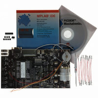
BOARD PICDEM FOR MECHATRONICS
Manufacturer
Microchip Technology
Specifications of DM163029
Main Purpose
Power Management, Motor Control
Embedded
*
Utilized Ic / Part
*
Primary Attributes
*
Secondary Attributes
*
Processor To Be Evaluated
PIC16F917
Interface Type
RS-232
Silicon Manufacturer
Microchip
Silicon Core Number
DM163029
Silicon Family Name
PICDEM
Kit Contents
PICDEM Mechatronics Board, MCU Samples, Software And Cables
Rohs Compliant
Yes
Lead Free Status / RoHS Status
Lead free / RoHS Compliant
Lead Free Status / RoHS Status
Lead free / RoHS Compliant, Lead free / RoHS Compliant
Available stocks
Company
Part Number
Manufacturer
Quantity
Price
Company:

Part Number:
DM163029
Manufacturer:
Microchip Technology
Quantity:
135
Company:
Part Number:
DM163029
Manufacturer:
MICROCHIP
Quantity:
12 000


© 2006 Microchip Technology Inc.
2.3.7
This project demonstrates the various ways to drive a bipolar stepper motor. There are
several ways to step a stepper motor, the most basic of which is single stepping, or
moving the motor in one-step increments. If a motor is specified as a 7.5
degrees-per-step motor, then single stepping the motor will result in moving the shaft
of the motor 7.5 degrees per step. Half stepping the same motor would result in a 3.75
degrees step.
Torque and current are linearly related for a stepper motor. Therefore, if two sinusoidal
currents are applied to the windings, offset by a 90 degree phase shift relative to one
another, then the stepper motor will have constant torque as it turns. This results in a
very smooth rotation of the shaft. Applying current to the windings in this way is referred
to as sine-cosine microstepping.
Objectives
1. Single-step a stepping motor.
2. Half-step the motor.
3. Micro-step the motor.
Applicable Technical Documents
Stepping Motor Fundamentals Application Note, AN907 (DS00907)
Stepper Motor Control Using the PIC16F684 Application Note, AN906 (DS00906)
Jumper Configuration
• AN0 (J13) to POT1 (J4)
• RA4 (J13) to SW2 (J4)
• RD7 (J10) to P1 (J1)
• RD6 (J10) to P2 (J1)
• RD5 (J10) to P3 (J1)
• RD4 (J10) to P4 (J1)
• CCP1 (J10) to PWM1 (J1)
• CCP2 (J10) to PWM3 (J1)
• Place three shunts (two pin jumpers) vertically on J2 where it is labeled “Connect
• Place three shunts (two pin jumpers) vertically on J3 where it is labeled “Connect
• Connect the BROWN lead of the stepper motor to Drive 1 (P9).
• Connect the ORANGE lead of the stepper motor to Drive 2 (P10).
• Connect the RED lead of the stepper motor to Drive 3 (P12).
• Connect the YELLOW lead of the stepper motor to Drive 4 (P11).
• Connect the right and center pins of JP8 using a shunt.
for Full-Bridge”.
for Full-Bridge”.
Project 7: Stepper Motor Control: Single Stepping, Half
Stepping and Microstepping
Example Projects
DS51557C-page 35
Related parts for DM163029
Image
Part Number
Description
Manufacturer
Datasheet
Request
R

Part Number:
Description:
Manufacturer:
Microchip Technology Inc.
Datasheet:
Part Number:
Description:
Manufacturer:
Microchip Technology Inc.
Datasheet:
Part Number:
Description:
Manufacturer:
Microchip Technology Inc.
Datasheet:
Part Number:
Description:
Manufacturer:
Microchip Technology Inc.
Datasheet:
Part Number:
Description:
Manufacturer:
Microchip Technology Inc.
Datasheet:
Part Number:
Description:
Manufacturer:
Microchip Technology Inc.
Datasheet:
Part Number:
Description:
Manufacturer:
Microchip Technology Inc.
Datasheet:
Part Number:
Description:
Manufacturer:
Microchip Technology Inc.
Datasheet: