DM163029 Microchip Technology, DM163029 Datasheet - Page 16
DM163029
Manufacturer Part Number
DM163029
Description
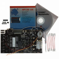
BOARD PICDEM FOR MECHATRONICS
Manufacturer
Microchip Technology
Specifications of DM163029
Main Purpose
Power Management, Motor Control
Embedded
*
Utilized Ic / Part
*
Primary Attributes
*
Secondary Attributes
*
Processor To Be Evaluated
PIC16F917
Interface Type
RS-232
Silicon Manufacturer
Microchip
Silicon Core Number
DM163029
Silicon Family Name
PICDEM
Kit Contents
PICDEM Mechatronics Board, MCU Samples, Software And Cables
Rohs Compliant
Yes
Lead Free Status / RoHS Status
Lead free / RoHS Compliant
Lead Free Status / RoHS Status
Lead free / RoHS Compliant, Lead free / RoHS Compliant
Available stocks
Company
Part Number
Manufacturer
Quantity
Price
Company:

Part Number:
DM163029
Manufacturer:
Microchip Technology
Quantity:
135
Company:
Part Number:
DM163029
Manufacturer:
MICROCHIP
Quantity:
12 000


PICDEM
1.6
1.7
DS51557C-page 12
REQUIRED TOOLS
PICDEM™ MECHATRONICS SETUP
TM
The reasons for requiring you to use the provided jumpers to connect components to
the microcontroller are three-fold.
1. You will gain knowledge and experience by physically connecting components to
2. There are more peripherals than pins on the microcontrollers so that you can do
3. Should you choose to use the board to experiment on your own, the board allows
One of the following programming tools is needed in order to complete the projects in
the next chapter:
• PICkit™ 2 Microcontroller Programmer (Part# DV164120)
• MPLAB
Figures 1-3 and 1-4 illustrate how to connect each of these tools to the PICDEM
Mechatronics Demo Board.
Please take a moment to review the following steps, prior to using the board. These
steps ensure the board is configured correctly before beginning the projects.
1.7.1
Remove all 2-pin shunts (jumpers), except for JP8. On JP8, the shunt should be
connected in the right most position (indicated by the “+5V” label), which ensures that
the drive stage is powered by +5 V
1.7.2
Supply power to the board in one of the following ways:
• Connect a 9-12 V
• Connect a 9-12 V
• Connect a 9 V
• Connect a 5 V
When power is initially connected, the “PWR ON” LED should light up. The “FAULT”
LED in the over-current sense circuit will also be on when the board is powered up.
Clear the Fault by pressing SW5 (CLR FAULT) switch. The board is now properly
configured for the projects.
Mechatronics Demo Board User’s Guide
9 V
is grounded externally and positive internally.
terminals.
the microcontroller.
more with the board.
you the flexibility to do so. You can try experimenting with peripherals not
covered in the projects in Chapter 2. “Example Projects”.
DC
power supply and serial cable)
®
Jumper Settings
Board Power-Up
ICD 2 In-Circuit Debugger/Programmer (Part# DV164007 includes a
DC
DC
DC
DC
battery to the battery connector.
(1.2 amp minimum) supply to TP2 or TP3.
(0.75 amp minimum) supply via J9. The connector’s polarity
(0.75 amp minimum) supply to the P21 and P20 screw
DC
.
© 2006 Microchip Technology Inc.
Related parts for DM163029
Image
Part Number
Description
Manufacturer
Datasheet
Request
R

Part Number:
Description:
Manufacturer:
Microchip Technology Inc.
Datasheet:
Part Number:
Description:
Manufacturer:
Microchip Technology Inc.
Datasheet:
Part Number:
Description:
Manufacturer:
Microchip Technology Inc.
Datasheet:
Part Number:
Description:
Manufacturer:
Microchip Technology Inc.
Datasheet:
Part Number:
Description:
Manufacturer:
Microchip Technology Inc.
Datasheet:
Part Number:
Description:
Manufacturer:
Microchip Technology Inc.
Datasheet:
Part Number:
Description:
Manufacturer:
Microchip Technology Inc.
Datasheet:
Part Number:
Description:
Manufacturer:
Microchip Technology Inc.
Datasheet: