STEVAL-ISF002V1 STMicroelectronics, STEVAL-ISF002V1 Datasheet - Page 5
STEVAL-ISF002V1
Manufacturer Part Number
STEVAL-ISF002V1
Description
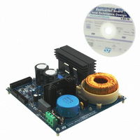
BOARD EVALUATION
Manufacturer
STMicroelectronics
Specifications of STEVAL-ISF002V1
Main Purpose
*
Embedded
*
Utilized Ic / Part
*
Primary Attributes
*
Secondary Attributes
*
Product
Power Management Modules
Lead Free Status / RoHS Status
Lead free / RoHS Compliant
Other names
497-10422
Available stocks
Company
Part Number
Manufacturer
Quantity
Price


UM0877
List of figures
Figure 1.
Figure 2.
Figure 3.
Figure 4.
Figure 5.
Figure 6.
Figure 7.
Figure 8.
Figure 9.
Figure 10.
Figure 11.
Figure 12.
Figure 13.
Figure 14.
Figure 15.
Figure 16.
Figure 17.
Figure 18.
Figure 19.
Figure 20.
Figure 21.
Figure 22.
Figure 23.
Figure 24.
Figure 25.
Figure 26.
Figure 27.
Figure 28.
Figure 29.
Figure 30.
Figure 31.
Figure 32.
Figure 33.
Figure 34.
Figure 35.
Figure 36.
Figure 37.
Figure 38.
Figure 39.
Figure 40.
Figure 41.
Figure 42.
Figure 43.
Figure 44.
Figure 45.
Figure 46.
Typical AC to DC rectification without PFC. . . . . . . . . . . . . . . . . . . . . . . . . . . . . . . . . . . . . . 8
Scheme of AC to DC boost converter topology . . . . . . . . . . . . . . . . . . . . . . . . . . . . . . . . . . 9
AC to DC boost converter signals with CCM PFC - output VDC, input Vac and inductor
current (time scale = 5 ms) . . . . . . . . . . . . . . . . . . . . . . . . . . . . . . . . . . . . . . . . . . . . . . . . . . 9
AC to DC boost converter signals with CCM PFC - inductor current and power MOSFET
gate command (time scale = 10 µs) . . . . . . . . . . . . . . . . . . . . . . . . . . . . . . . . . . . . . . . . . . . 9
Digital PFC implementation scheme. . . . . . . . . . . . . . . . . . . . . . . . . . . . . . . . . . . . . . . . . . 10
Block diagram of the voltage and current PI regulator . . . . . . . . . . . . . . . . . . . . . . . . . . . . 10
STEVAL-ISF002V1 . . . . . . . . . . . . . . . . . . . . . . . . . . . . . . . . . . . . . . . . . . . . . . . . . . . . . . . 11
Vin connector . . . . . . . . . . . . . . . . . . . . . . . . . . . . . . . . . . . . . . . . . . . . . . . . . . . . . . . . . . . 16
Vout connector . . . . . . . . . . . . . . . . . . . . . . . . . . . . . . . . . . . . . . . . . . . . . . . . . . . . . . . . . . 16
MC + PFC connector . . . . . . . . . . . . . . . . . . . . . . . . . . . . . . . . . . . . . . . . . . . . . . . . . . . . . 17
MC connector only . . . . . . . . . . . . . . . . . . . . . . . . . . . . . . . . . . . . . . . . . . . . . . . . . . . . . . . 17
STEVAL-ISF001V1 block diagram . . . . . . . . . . . . . . . . . . . . . . . . . . . . . . . . . . . . . . . . . . . 18
STEVAL-ISF002V1 - power supply section . . . . . . . . . . . . . . . . . . . . . . . . . . . . . . . . . . . . 19
STEVAL-ISF002V1 - input voltage sensing section . . . . . . . . . . . . . . . . . . . . . . . . . . . . . . 20
STEVAL-IHM022V1 - input voltage sensing section . . . . . . . . . . . . . . . . . . . . . . . . . . . . . 20
STEVAL-ISF002V1 - output voltage sensing section . . . . . . . . . . . . . . . . . . . . . . . . . . . . . 21
STEVAL-IHM022V1 - output voltage sensing section . . . . . . . . . . . . . . . . . . . . . . . . . . . . 21
STEVAL-ISF002V1 - PFC current sensing section . . . . . . . . . . . . . . . . . . . . . . . . . . . . . . 22
STEVAL-IHM022V1 - PFC current sensing section . . . . . . . . . . . . . . . . . . . . . . . . . . . . . . 22
STEVAL-ISF002V1 - PFC power MOSFET driving section . . . . . . . . . . . . . . . . . . . . . . . . 24
STEVAL-ISF002V1 - overcurrent protection section . . . . . . . . . . . . . . . . . . . . . . . . . . . . . 25
STEVAL-ISF002V1 - vin zero crossing detection section. . . . . . . . . . . . . . . . . . . . . . . . . . 26
Vin zero crossing detection (without load) . . . . . . . . . . . . . . . . . . . . . . . . . . . . . . . . . . . . . 27
Vin zero crossing detection (with load) . . . . . . . . . . . . . . . . . . . . . . . . . . . . . . . . . . . . . . . . 27
STEVAL-IHM022V1 . . . . . . . . . . . . . . . . . . . . . . . . . . . . . . . . . . . . . . . . . . . . . . . . . . . . . . 29
Output voltage soft-start methodology . . . . . . . . . . . . . . . . . . . . . . . . . . . . . . . . . . . . . . . . 31
PFC states . . . . . . . . . . . . . . . . . . . . . . . . . . . . . . . . . . . . . . . . . . . . . . . . . . . . . . . . . . . . . 32
Use of peripherals for digital PFC . . . . . . . . . . . . . . . . . . . . . . . . . . . . . . . . . . . . . . . . . . . . 33
PFC firmware flowchart . . . . . . . . . . . . . . . . . . . . . . . . . . . . . . . . . . . . . . . . . . . . . . . . . . . 38
Digital PFC timing . . . . . . . . . . . . . . . . . . . . . . . . . . . . . . . . . . . . . . . . . . . . . . . . . . . . . . . . 39
Hardware connections for firmware downloading . . . . . . . . . . . . . . . . . . . . . . . . . . . . . . . . 41
Opening the workspace file . . . . . . . . . . . . . . . . . . . . . . . . . . . . . . . . . . . . . . . . . . . . . . . . 42
Downloading and debugging the firmware . . . . . . . . . . . . . . . . . . . . . . . . . . . . . . . . . . . . . 42
Connecting the various system components . . . . . . . . . . . . . . . . . . . . . . . . . . . . . . . . . . . 43
Hardware elements of the control board. . . . . . . . . . . . . . . . . . . . . . . . . . . . . . . . . . . . . . . 44
LCD after startup . . . . . . . . . . . . . . . . . . . . . . . . . . . . . . . . . . . . . . . . . . . . . . . . . . . . . . . . 45
LCD during running of the digital PFC . . . . . . . . . . . . . . . . . . . . . . . . . . . . . . . . . . . . . . . . 45
LCD after an overcurrent . . . . . . . . . . . . . . . . . . . . . . . . . . . . . . . . . . . . . . . . . . . . . . . . . . 46
Test setup block diagram . . . . . . . . . . . . . . . . . . . . . . . . . . . . . . . . . . . . . . . . . . . . . . . . . . 47
185 Vrms at 50 Hz as input - 1400 W as output load . . . . . . . . . . . . . . . . . . . . . . . . . . . . . 47
230 Vrms at 50 Hz as input - 1400 W as output load . . . . . . . . . . . . . . . . . . . . . . . . . . . . . 48
265 Vrms at 50 Hz as input - 1400 W as output load . . . . . . . . . . . . . . . . . . . . . . . . . . . . . 48
STEVAL-ISF00V1 schematic . . . . . . . . . . . . . . . . . . . . . . . . . . . . . . . . . . . . . . . . . . . . . . . 50
STEVAL-ISF002V1 layout . . . . . . . . . . . . . . . . . . . . . . . . . . . . . . . . . . . . . . . . . . . . . . . . . 51
Technical sheet of PFC inductor - page 1 of 2 . . . . . . . . . . . . . . . . . . . . . . . . . . . . . . . . . . 59
Technical sheet of PFC inductor - page 2 of 2 . . . . . . . . . . . . . . . . . . . . . . . . . . . . . . . . . . 60
Doc ID 16854 Rev 1
List of figures
5/62
Related parts for STEVAL-ISF002V1
Image
Part Number
Description
Manufacturer
Datasheet
Request
R

Part Number:
Description:
BOARD RGB CTR ST7,STP08C596MTR
Manufacturer:
STMicroelectronics
Datasheet:

Part Number:
Description:
Power Management IC Development Tools Full Speed USB to RS232 Bridge Demo
Manufacturer:
STMicroelectronics
Datasheet:
Part Number:
Description:
Power Management IC Development Tools 2.5W solar eval BRD USB SPV1040 LD39050
Manufacturer:
STMicroelectronics
Datasheet:

Part Number:
Description:
BOARD EVAL FOR MEMS SENSORS
Manufacturer:
STMicroelectronics
Datasheet:

Part Number:
Description:
KIT DEV STARTER ST10F276Z5
Manufacturer:
STMicroelectronics
Datasheet:

Part Number:
Description:
BOARD EVAL HDMI $ VIDEO SWITCH
Manufacturer:
STMicroelectronics
Datasheet:

Part Number:
Description:
BOARD DEMO ACCELEROMETER DIL24
Manufacturer:
STMicroelectronics
Datasheet:

Part Number:
Description:
BOARD STLM75/STDS75/ST72F651
Manufacturer:
STMicroelectronics
Datasheet:

Part Number:
Description:
EVAL BOARD 3AXIS MEMS ACCELLRMTR
Manufacturer:
STMicroelectronics
Datasheet:

Part Number:
Description:
BOARD EVAL 8BIT MICRO + TDE1708
Manufacturer:
STMicroelectronics
Datasheet:
Part Number:
Description:
STMicroelectronics [RIPPLE-CARRY BINARY COUNTER/DIVIDERS]
Manufacturer:
STMicroelectronics
Datasheet:
Part Number:
Description:
STMicroelectronics [LIQUID-CRYSTAL DISPLAY DRIVERS]
Manufacturer:
STMicroelectronics
Datasheet:
Part Number:
Description:
BOARD EVAL FOR MEMS SENSORS
Manufacturer:
STMicroelectronics
Datasheet: