STEVAL-ISF002V1 STMicroelectronics, STEVAL-ISF002V1 Datasheet - Page 9
STEVAL-ISF002V1
Manufacturer Part Number
STEVAL-ISF002V1
Description
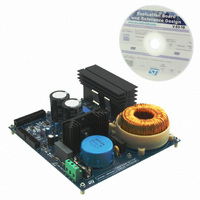
BOARD EVALUATION
Manufacturer
STMicroelectronics
Specifications of STEVAL-ISF002V1
Main Purpose
*
Embedded
*
Utilized Ic / Part
*
Primary Attributes
*
Secondary Attributes
*
Product
Power Management Modules
Lead Free Status / RoHS Status
Lead free / RoHS Compliant
Other names
497-10422
Available stocks
Company
Part Number
Manufacturer
Quantity
Price


UM0877
2.2
Figure 3.
Figure 2.
PFC with digital approach
●
From a theoretical point of view, it could be possible to replace an existing analog solution
made up of discrete components with ST’s digital solution, in which case, other than the
PFC control, the same MCU would also manage the main application.
To perform a digital power factor corrector, a microcontroller needs to have information
about three main system parameters. These are the output DC voltage, the input AC voltage
and the inductor current.
These parameters, appropriately scaled down, are managed by the microcontroller that
modulates the switching of the MOSFET to have the input current in phase with the input AC
voltage while keeping the output DC voltage to a fixed and stable value.
A generic implementation scheme for a digital PFC is shown in
AC to DC boost converter signals
with CCM PFC - output VDC, input
Vac and inductor current
(time scale = 5 ms)
A digital implementation for a PFC gives some advantages.
–
–
–
Easy implementation of sophisticated control algorithms.
Quick software modifications to meet specific requirements.
Simple integration with other applications.
Scheme of AC to DC boost converter topology
Doc ID 16854 Rev 1
Figure 4.
PFC basics and operating principles
AC to DC boost converter signals
with CCM PFC - inductor current
and power MOSFET gate command
(time scale = 10 µs)
Figure
5.
9/62
Related parts for STEVAL-ISF002V1
Image
Part Number
Description
Manufacturer
Datasheet
Request
R

Part Number:
Description:
BOARD RGB CTR ST7,STP08C596MTR
Manufacturer:
STMicroelectronics
Datasheet:

Part Number:
Description:
Power Management IC Development Tools Full Speed USB to RS232 Bridge Demo
Manufacturer:
STMicroelectronics
Datasheet:
Part Number:
Description:
Power Management IC Development Tools 2.5W solar eval BRD USB SPV1040 LD39050
Manufacturer:
STMicroelectronics
Datasheet:

Part Number:
Description:
BOARD EVAL FOR MEMS SENSORS
Manufacturer:
STMicroelectronics
Datasheet:

Part Number:
Description:
KIT DEV STARTER ST10F276Z5
Manufacturer:
STMicroelectronics
Datasheet:

Part Number:
Description:
BOARD EVAL HDMI $ VIDEO SWITCH
Manufacturer:
STMicroelectronics
Datasheet:

Part Number:
Description:
BOARD DEMO ACCELEROMETER DIL24
Manufacturer:
STMicroelectronics
Datasheet:

Part Number:
Description:
BOARD STLM75/STDS75/ST72F651
Manufacturer:
STMicroelectronics
Datasheet:

Part Number:
Description:
EVAL BOARD 3AXIS MEMS ACCELLRMTR
Manufacturer:
STMicroelectronics
Datasheet:

Part Number:
Description:
BOARD EVAL 8BIT MICRO + TDE1708
Manufacturer:
STMicroelectronics
Datasheet:
Part Number:
Description:
STMicroelectronics [RIPPLE-CARRY BINARY COUNTER/DIVIDERS]
Manufacturer:
STMicroelectronics
Datasheet:
Part Number:
Description:
STMicroelectronics [LIQUID-CRYSTAL DISPLAY DRIVERS]
Manufacturer:
STMicroelectronics
Datasheet:
Part Number:
Description:
BOARD EVAL FOR MEMS SENSORS
Manufacturer:
STMicroelectronics
Datasheet: