EVB9303 SMSC, EVB9303 Datasheet - Page 110
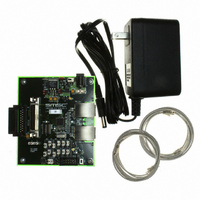
EVB9303
Manufacturer Part Number
EVB9303
Description
EVALUATION BOARD FOR LAN9303
Manufacturer
SMSC
Specifications of EVB9303
Main Purpose
Interface, Ethernet
Embedded
No
Utilized Ic / Part
LAN9303
Primary Attributes
3 Ports, 100BASE-TX/10BASE-T, Managed
Secondary Attributes
Full Duplex and HP Auto-MDIX Support, 10BASE-T and 100BASE-TX
Lead Free Status / Rohs Status
Lead free / RoHS Compliant
Other names
638-1095


Revision 1.4 (07-07-10)
8.3.5
8.3.6
8.3.6.1
8.3.6.2
A
C
K
D
7
D
6
Data Byte
D
5
Data Cycle
D
4
Figure 8.3
D
3
For a register level description of a write operation, refer to
Controller Operation," on page
Wait State Generation
The serial clock is also used as an input as it can be held low by the slave device in order to wait-
state the data cycle. Once the slave has data available or is ready to receive, it will release the clock.
Assuming the masters clock low time is also expired, the clock will rise and the cycle will continue. If
the slave device holds the clock low for more than 30mS, the current command sequence is aborted
and the
(E2P_CMD)
I
Since the I
master I
try to access the bus at the same time. The I
mechanisms: bus busy, clock synchronization and bus arbitration.
Note: The timing parameters referred to in the following subsections refer to the detailed timing
Bus Busy
A master may start a transfer only if the bus is not busy. The bus is considered to be busy after the
START condition and is considered to be free again t
mode value of 4.7us is used for t
Following reset, it is unknown if the bus is actually busy, since the START condition may have been
missed. Therefore, following reset, the bus is initially considered busy and is considered free t
after the STOP condition or if clock and data are seen high for 4mS. In order to speed up device
configuration, if the management mode is not I
considered free).
Clock Synchronization
Clock synchronization is used, since both masters may be generating different clock frequencies.
When the clock is driven low by one master, each other active master will restart its low timer and also
drive the clock low. Each master will drive the clock low for its minimum low time and then release it.
The clock line will not go high until all masters have released it. The slowest master therefore
determines the actual low time. Devices with shorter low timers will wait. Once the clock goes high,
each master will start its high timer. The first master to reach its high time will once again drive the
clock low. The fastest master therefore determines the actual high time. The process then repeats.
Clock synchronization is similar to the cycle stretching that can be done by a slave device, with the
2
C Bus Arbitration and Clock Synchronization
D
2
D
1
D
0
information presented in the NXP I
2
EEPROM Controller Timeout (EPC_TIMEOUT)
C devices on the bus (the device and the Host). There exists the potential that both masters
A
C
K
illustrates typical I
2
C Master and the I
is set.
P
S 1 0 1 0
Control Byte
Poll Cycle
Chip / Block
Select Bits
Figure 8.5 I
0 0 0
2
Small Form Factor Three Port 10/100 Managed Ethernet Switch with Single MII/RMII/Turbo MII
C EEPROM byte write.
111.
2
C Slave Serial interfaces share common pins, there are at least two
DATASHEET
buf
0
R/~W
2
C EEPROM Byte Write
C
A
K
since the EEPROM master runs at the standard mode rate.
S 1 0 1 0
110
2
C-Bus Specification .
Control Byte
Poll Cycle
Chip / Block
Select Bits
2
2
C, this check is not performed (the bus is initially
C specification handles this situation with three
buf
0 0 0
time after the STOP condition. The standard
bit in the
0
R/~W
Section 8.3.7, "I2C Master EEPROM
A
C
K
...
EEPROM Command Register
S 1 0 1 0
Control Byte
SMSC LAN9303/LAN9303i
Poll Cycle
Chip / Block
Select Bits
0 0 0
0
Conclude
R/~W
Datasheet
A
C
K
buf
S P
time
Related parts for EVB9303
Image
Part Number
Description
Manufacturer
Datasheet
Request
R


Part Number:
Description:
FAST ETHERNET PHYSICAL LAYER DEVICE
Manufacturer:
SMSC Corporation
Datasheet:
Part Number:
Description:
357-036-542-201 CARDEDGE 36POS DL .156 BLK LOPRO
Manufacturer:
SMSC Corporation
Datasheet:
Part Number:
Description:
357-036-542-201 CARDEDGE 36POS DL .156 BLK LOPRO
Manufacturer:
SMSC Corporation
Datasheet:
Part Number:
Description:
357-036-542-201 CARDEDGE 36POS DL .156 BLK LOPRO
Manufacturer:
SMSC Corporation
Datasheet:
Part Number:
Description:
4-PORT USB2.0 HUB CONTROLLER
Manufacturer:
SMSC Corporation
Datasheet:
Part Number:
Description:
Manufacturer:
SMSC Corporation
Datasheet:
Part Number:
Description:
Manufacturer:
SMSC Corporation
Datasheet:
Part Number:
Description:
FDC37C672ENHANCED SUPER I/O CONTROLLER WITH FAST IR
Manufacturer:
SMSC Corporation
Datasheet:
Part Number:
Description:
COM90C66LJPARCNET Controller/Transceiver with AT Interface and On-Chip RAM
Manufacturer:
SMSC Corporation
Datasheet:
Part Number:
Description:
Manufacturer:
SMSC Corporation
Datasheet:
Part Number:
Description:
Manufacturer:
SMSC Corporation
Datasheet:
Part Number:
Description:
Manufacturer:
SMSC Corporation
Datasheet:
Part Number:
Description:
Manufacturer:
SMSC Corporation
Datasheet: