EVB9303 SMSC, EVB9303 Datasheet - Page 133
EVB9303
Manufacturer Part Number
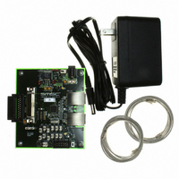
EVB9303
Description
EVALUATION BOARD FOR LAN9303
Manufacturer
SMSC
Specifications of EVB9303
Main Purpose
Interface, Ethernet
Embedded
No
Utilized Ic / Part
LAN9303
Primary Attributes
3 Ports, 100BASE-TX/10BASE-T, Managed
Secondary Attributes
Full Duplex and HP Auto-MDIX Support, 10BASE-T and 100BASE-TX
Lead Free Status / Rohs Status
Lead free / RoHS Compliant
Other names
638-1095


Small Form Factor Three Port 10/100 Managed Ethernet Switch with Single MII/RMII/Turbo MII
Datasheet
SMSC LAN9303/LAN9303i
12.2.1.1
12.3
(GPIO5)
(GPIO4)
(GPIO3)
(GPIO2)
(GPIO1)
(GPIO0)
LED5
LED4
LED3
LED2
LED1
LED0
GPIO Interrupt Polarity
The interrupt polarity can be set for each individual GPIO via the
(GPIO_INT_POL[5:0])
a high logic level on the GPIO pin will set the corresponding interrupt bit in the
Interrupt Status and Enable Register
GPIO pin will set the corresponding interrupt bit.
Each GPIO can be individually selected to function as a LED. These pins are configured as LED
outputs by setting the corresponding
Register
source output and the GPIO related input buffer and pull-up are disabled. The default configuration,
including polarity, is determined by input straps or EEPROM entries. Refer to
page 45
The functions associated with each LED pin are configurable via the
bits of the
to indicate various port related functions. These functions are described in
detailed definition of each indication type.
The default values of the
of the
LED_en_strap[5:0]
(LED_CFG)
on page
The various LED indication functions shown in
LED Operation
Full-duplex / Collision
Full-duplex / Collision
LED Configuration Register (LED_CFG)
Link / Activity
Link / Activity
147.
for additional information.
(LED_CFG). When configured as a LED, the pin is either a push-pull or open-drain / open-
LED Configuration Register
Speed
Speed
Port 2
Port 2
Port 2
Port 1
Port 1
Port 1
and its related straps, refer to
00b
Table 12.1 LED Operation as a Function of LED_FUN[1:0]
configuration straps. For more information on the
bits in the
LED Function 1-0 (LED_FUN[1:0])
Full-duplex / Collision
Full-duplex / Collision
100Link / Activity
100Link / Activity
10Link / Activity
10Link / Activity
General Purpose I/O Configuration Register
DATASHEET
Port 2
Port 2
Port 2
Port 1
Port 1
Port 1
01b
(GPIO_INT_STS_EN). When cleared, a low logic level on the
(LED_CFG). These bits allow the configuration of each LED pin
LED Enable 5-0 (LED_EN[5:0])
133
Section 13.2.2.4, "LED Configuration Register (LED_CFG),"
Table 12.1
are determined by the
Link / Activity
Link / Activity
are described in the following sections.
Speed
Speed
Port 0
Port 2
Port 2
Port 0
Port 1
Port 1
and
10b
RX
TX
LED Enable 5-0 (LED_EN[5:0])
LED Function 1-0 (LED_FUN[1:0])
bit in the
GPIO Interrupt Polarity 5-0
LED Configuration Register
LED_fun_strap[1:0]
Table
(GPIO_CFG). When set,
Configuration Straps on
General Purpose I/O
Revision 1.4 (07-07-10)
12.1, followed by a
LED Configuration
RX_DV
RX_DV
RX_DV
TX_EN
TX_EN
TX_EN
Port 0
Port 2
Port 2
Port 0
Port 1
Port 1
11b
and
bits
Related parts for EVB9303
Image
Part Number
Description
Manufacturer
Datasheet
Request
R


Part Number:
Description:
FAST ETHERNET PHYSICAL LAYER DEVICE
Manufacturer:
SMSC Corporation
Datasheet:
Part Number:
Description:
357-036-542-201 CARDEDGE 36POS DL .156 BLK LOPRO
Manufacturer:
SMSC Corporation
Datasheet:
Part Number:
Description:
357-036-542-201 CARDEDGE 36POS DL .156 BLK LOPRO
Manufacturer:
SMSC Corporation
Datasheet:
Part Number:
Description:
357-036-542-201 CARDEDGE 36POS DL .156 BLK LOPRO
Manufacturer:
SMSC Corporation
Datasheet:
Part Number:
Description:
4-PORT USB2.0 HUB CONTROLLER
Manufacturer:
SMSC Corporation
Datasheet:
Part Number:
Description:
Manufacturer:
SMSC Corporation
Datasheet:
Part Number:
Description:
Manufacturer:
SMSC Corporation
Datasheet:
Part Number:
Description:
FDC37C672ENHANCED SUPER I/O CONTROLLER WITH FAST IR
Manufacturer:
SMSC Corporation
Datasheet:
Part Number:
Description:
COM90C66LJPARCNET Controller/Transceiver with AT Interface and On-Chip RAM
Manufacturer:
SMSC Corporation
Datasheet:
Part Number:
Description:
Manufacturer:
SMSC Corporation
Datasheet:
Part Number:
Description:
Manufacturer:
SMSC Corporation
Datasheet:
Part Number:
Description:
Manufacturer:
SMSC Corporation
Datasheet:
Part Number:
Description:
Manufacturer:
SMSC Corporation
Datasheet: