EVB9303 SMSC, EVB9303 Datasheet - Page 55
EVB9303
Manufacturer Part Number
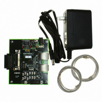
EVB9303
Description
EVALUATION BOARD FOR LAN9303
Manufacturer
SMSC
Specifications of EVB9303
Main Purpose
Interface, Ethernet
Embedded
No
Utilized Ic / Part
LAN9303
Primary Attributes
3 Ports, 100BASE-TX/10BASE-T, Managed
Secondary Attributes
Full Duplex and HP Auto-MDIX Support, 10BASE-T and 100BASE-TX
Lead Free Status / Rohs Status
Lead free / RoHS Compliant
Other names
638-1095


Small Form Factor Three Port 10/100 Managed Ethernet Switch with Single MII/RMII/Turbo MII
Datasheet
Chapter 5 System Interrupts
SMSC LAN9303/LAN9303i
5.1
5.2
This chapter describes the system interrupt structure. The device provides a multi-tier programmable
interrupt structure which is controlled by the System Interrupt Controller. The programmable system
interrupts are generated internally by the various sub-modules and can be configured to generate a
single external host interrupt via the IRQ interrupt output pin. The programmable nature of the host
interrupt provides the user with the ability to optimize performance dependent upon the application
requirements. The IRQ interrupt buffer type, polarity, and de-assertion interval are modifiable. The IRQ
interrupt can be configured as an open-drain output to facilitate the sharing of interrupts with other
devices. All internal interrupts are maskable and capable of triggering the IRQ interrupt.
The device is capable of generating the following interrupt types:
All interrupts are accessed and configured via registers arranged into a multi-tier, branch-like structure,
as shown in
(INT_STS),
The
enable/disable all interrupts from the various sub-modules, combining them together to create the IRQ
interrupt. These registers provide direct interrupt access/configuration to the General Purpose Timer,
software, and device ready interrupts. These interrupts can be monitored, enabled/disabled, and
cleared, directly within these two registers. In addition, interrupt event indications are provided for the
Switch Fabric, Port 1 & 2 Ethernet PHYs, and GPIO interrupts. These interrupts differ in that the
interrupt sources are generated and cleared in other sub-block registers. The
(INT_STS)
and requires the software to poll an additional sub-module interrupt register (as shown in
to determine the exact interrupt source and clear it. For interrupts which involve multiple registers, only
after the interrupt has been serviced and cleared at its source will it be cleared in the
Register
The
output pin as well as configuring its properties. This register allows the modification of the IRQ pin
buffer type, polarity, and de-assertion interval. The de-assertion timer guarantees a minimum interrupt
de-assertion period for the IRQ output and is programmable via the
(INT_DEAS)
de-assertion timer. The de-assertion interval starts when the IRQ pin de-asserts, regardless of the
reason.
Functional Overview
Interrupt Sources
Switch Fabric Interrupts
Ethernet PHY Interrupts
GPIO Interrupts
General Purpose Timer Interrupt
Software Interrupt
Device Ready Interrupt
Interrupt Configuration Register (IRQ_CFG)
Interrupt Status Register (INT_STS)
(INT_STS).
does not provide details on what specific event within the sub-module caused the interrupt,
Interrupt Enable Register
field of the
Figure
(GPIO[5:0])
5.1. At the top level of the interrupt structure are the
(General Purpose)
Interrupt Configuration Register
(Buffer Manager, Switch Engine, and Port 2,1,0 MACs)
(Port 1,2 PHYs)
DATASHEET
(GPT)
(INT_EN), and
55
and
Interrupt Enable Register (INT_EN)
is responsible for enabling/disabling the IRQ interrupt
Interrupt Configuration Register
(IRQ_CFG). A setting of all zeros disables the
Interrupt De-assertion Interval
Interrupt Status Register
Interrupt Status Register
Revision 1.4 (07-07-10)
(IRQ_CFG).
aggregate and
Interrupt Status
Figure
5.1)
Related parts for EVB9303
Image
Part Number
Description
Manufacturer
Datasheet
Request
R


Part Number:
Description:
FAST ETHERNET PHYSICAL LAYER DEVICE
Manufacturer:
SMSC Corporation
Datasheet:
Part Number:
Description:
357-036-542-201 CARDEDGE 36POS DL .156 BLK LOPRO
Manufacturer:
SMSC Corporation
Datasheet:
Part Number:
Description:
357-036-542-201 CARDEDGE 36POS DL .156 BLK LOPRO
Manufacturer:
SMSC Corporation
Datasheet:
Part Number:
Description:
357-036-542-201 CARDEDGE 36POS DL .156 BLK LOPRO
Manufacturer:
SMSC Corporation
Datasheet:
Part Number:
Description:
4-PORT USB2.0 HUB CONTROLLER
Manufacturer:
SMSC Corporation
Datasheet:
Part Number:
Description:
Manufacturer:
SMSC Corporation
Datasheet:
Part Number:
Description:
Manufacturer:
SMSC Corporation
Datasheet:
Part Number:
Description:
FDC37C672ENHANCED SUPER I/O CONTROLLER WITH FAST IR
Manufacturer:
SMSC Corporation
Datasheet:
Part Number:
Description:
COM90C66LJPARCNET Controller/Transceiver with AT Interface and On-Chip RAM
Manufacturer:
SMSC Corporation
Datasheet:
Part Number:
Description:
Manufacturer:
SMSC Corporation
Datasheet:
Part Number:
Description:
Manufacturer:
SMSC Corporation
Datasheet:
Part Number:
Description:
Manufacturer:
SMSC Corporation
Datasheet:
Part Number:
Description:
Manufacturer:
SMSC Corporation
Datasheet: