MCP3909RD-3PH1 Microchip Technology, MCP3909RD-3PH1 Datasheet - Page 37
MCP3909RD-3PH1
Manufacturer Part Number
MCP3909RD-3PH1
Description
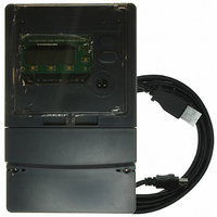
REF DESIGN MCP3909 3PH ENGY MTR
Manufacturer
Microchip Technology
Datasheets
1.MCP3909T-ISS.pdf
(44 pages)
2.MCP3909T-ISS.pdf
(104 pages)
3.MCP3909RD-3PH3.pdf
(88 pages)
Specifications of MCP3909RD-3PH1
Main Purpose
Power Management, Energy/Power Meter
Embedded
No
Utilized Ic / Part
MCP3909, PIC18F2520, PIC18F4550
Primary Attributes
3-Ph, 220 VAC, In Case, LCD, USB, GUI
Secondary Attributes
Opto-Isolated Interface for Safety
Operating Voltage
220 V
Operating Current
5 A
Description/function
Energy Meter
For Use With/related Products
MCP3909
Lead Free Status / RoHS Status
Not applicable / Not applicable


3.6
TABLE 3-1:
3.7
TABLE 3-2:
© 2009 Microchip Technology Inc.
Interrupt
Sync Field
Timer
Resource Name
System Clock
2 bytes
COMMUNICATION OF UART INTERFACE
RESOURCE CONFIGURATION
SPI2
SPI1
UART RX
UART TX
FRAME STRUCTURE OF COMMUNICATION PROTOCOL
CONFIGURATION OF MCU RESOURCES
Timer2
Timer3
TMR2
ADC
IC1
Command Type
The UART interface is used to communicate with the upper computer (MCU or PC). Via
the UART interface, the upper computer reads the measured parameters of the power
grid, and may also send system parameters and calibration parameters to the target
board as well.
The communication interface is a bidirectional interface based on UART, using
master/slave half-duplex mode. The baud rate is 19,200 bps, with 1 start bit, 8 data bits
and 1 stop bit. Communication is done by frames with non-fixed-length frame structure,
definition of which is shown in Table 3-1. The Communication protocol is specified in a
master-slave structure. The system in this design is the slave, and the upper computer
is the master. The master sends commands to the slave, and slave responds to the
master.
Each command is defined in Chapter 6. “Meter Communications Protocol”.
Details of the MCU resources used in this design and their configurations are listed in
Table 3-2.
1 byte
Interrupt
Priority
none
none
none
1
1
5
2
2
2
Fcy = 29.4912M, provided by an external 7.3728 Mz timer through an inter-
nal PLL frequency doubler.
System clock, used for timing. Its cycle is 10 ms. The interrupt flag may be
set in the IRS. Used to extend the indication of timer. Also used to deal with
UART reception overtime.
Used to detect ADC's sampling synchronization of neutral current. After the
frequency of the power grid is measured, the period of TMR3 is adjusted
accordingly. 16 points are sampled by ADC for each cycle of power grid.
ditto
Driven by a 3.2768 MHz clock. The MCP3909 device can generate
12.8 ksps of data output.
Sampling input capture. An interrupt is generated for every two MCP3909
device samplings. 6.4 ksps sampling rate is realized.
In fact, active power is cumulated at 6.4 ksps sampling rate (128 sampling
points each cycle at 50 Hz), but other parameters are cumulated at 3.2 ksps
sampling rate
Receive data of UART communication
Transmit data of UART communication
Detect current of neutral line
Used in communicating with the MCP390X device - set the MCP390X
device's modes and read A/D results
Unused, but the interface is reserved and may be used to communicate
with upper computer in substitution of the UART interface
Data Length
1 byte
Data Field
N bytes
Functional Description
Checkout Byte
1 byte
Firmware
DS51723A-page 37
End Byte
1 byte
Related parts for MCP3909RD-3PH1
Image
Part Number
Description
Manufacturer
Datasheet
Request
R

Part Number:
Description:
BOARD DES MCP3909 ENERGY METER
Manufacturer:
Microchip Technology
Datasheet:

Part Number:
Description:
REF DESIGN FOR MCP3909 W/18F2520
Manufacturer:
Microchip Technology
Datasheet:

Part Number:
Description:
Manufacturer:
Microchip Technology Inc.
Datasheet:
Part Number:
Description:
Manufacturer:
Microchip Technology Inc.
Datasheet:
Part Number:
Description:
Manufacturer:
Microchip Technology Inc.
Datasheet:
Part Number:
Description:
Manufacturer:
Microchip Technology Inc.
Datasheet:
Part Number:
Description:
Manufacturer:
Microchip Technology Inc.
Datasheet:
Part Number:
Description:
Manufacturer:
Microchip Technology Inc.
Datasheet:
Part Number:
Description:
Manufacturer:
Microchip Technology Inc.
Datasheet:
Part Number:
Description:
Manufacturer:
Microchip Technology Inc.
Datasheet: