MCP3909RD-3PH1 Microchip Technology, MCP3909RD-3PH1 Datasheet - Page 91
MCP3909RD-3PH1
Manufacturer Part Number
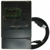
MCP3909RD-3PH1
Description
REF DESIGN MCP3909 3PH ENGY MTR
Manufacturer
Microchip Technology
Datasheets
1.MCP3909T-ISS.pdf
(44 pages)
2.MCP3909T-ISS.pdf
(104 pages)
3.MCP3909RD-3PH3.pdf
(88 pages)
Specifications of MCP3909RD-3PH1
Main Purpose
Power Management, Energy/Power Meter
Embedded
No
Utilized Ic / Part
MCP3909, PIC18F2520, PIC18F4550
Primary Attributes
3-Ph, 220 VAC, In Case, LCD, USB, GUI
Secondary Attributes
Opto-Isolated Interface for Safety
Operating Voltage
220 V
Operating Current
5 A
Description/function
Energy Meter
For Use With/related Products
MCP3909
Lead Free Status / RoHS Status
Not applicable / Not applicable


C.7
C.8
C.9
© 2009 Microchip Technology Inc.
MEASURING SECONDARY PARAMETERS
APPARENT POWER OF EACH PHASE AND TOTAL APPARENT POWER
POWER FACTOR OF EACH PHASE AND TOTAL POWER FACTOR
The methods of measuring parameters such as RMS values of voltage and current,
active power, reactive power and frequency have been discussed in previous sections.
These are primary parameters that need to be calculated from the original data. There
are some other parameters called secondary parameter, such as power factor of each
phase, total reactive power, total active power, total power factor, harmonic
components and cumulative energy. They are obtained indirectly from primary param-
eters.
The measurement of secondary parameters is discussed in this section.
C.7.0.1
For 3-phase 4-wire systems, 3-phase total active power and recative power are the
sum of power of each phase, respectively, which can be expressed as:
EQUATION C-54:
EQUATION C-55:
Apparent power is defined as:
EQUATION C-56:
Power factor is defined as the ratio of active power to apparent power. The definition
can be represented as shown in Equation C-57:
EQUATION C-57:
TOTAL ACTIVE POWER AND TOTAL REACTIVE POWER
Q
P
Power Calculation Theory
PF
=
S
=
=
Q
P
=
A
A
----------------------- -
+
+
Q
P
P
Q
2
2
B
+
P
B
+
+
+
p
Q
2
P
Q
2
C
C
DS51723A-page 91
Related parts for MCP3909RD-3PH1
Image
Part Number
Description
Manufacturer
Datasheet
Request
R

Part Number:
Description:
BOARD DES MCP3909 ENERGY METER
Manufacturer:
Microchip Technology
Datasheet:

Part Number:
Description:
REF DESIGN FOR MCP3909 W/18F2520
Manufacturer:
Microchip Technology
Datasheet:

Part Number:
Description:
Manufacturer:
Microchip Technology Inc.
Datasheet:
Part Number:
Description:
Manufacturer:
Microchip Technology Inc.
Datasheet:
Part Number:
Description:
Manufacturer:
Microchip Technology Inc.
Datasheet:
Part Number:
Description:
Manufacturer:
Microchip Technology Inc.
Datasheet:
Part Number:
Description:
Manufacturer:
Microchip Technology Inc.
Datasheet:
Part Number:
Description:
Manufacturer:
Microchip Technology Inc.
Datasheet:
Part Number:
Description:
Manufacturer:
Microchip Technology Inc.
Datasheet:
Part Number:
Description:
Manufacturer:
Microchip Technology Inc.
Datasheet: