MCP3909RD-3PH1 Microchip Technology, MCP3909RD-3PH1 Datasheet - Page 89
MCP3909RD-3PH1
Manufacturer Part Number
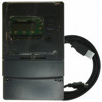
MCP3909RD-3PH1
Description
REF DESIGN MCP3909 3PH ENGY MTR
Manufacturer
Microchip Technology
Datasheets
1.MCP3909T-ISS.pdf
(44 pages)
2.MCP3909T-ISS.pdf
(104 pages)
3.MCP3909RD-3PH3.pdf
(88 pages)
Specifications of MCP3909RD-3PH1
Main Purpose
Power Management, Energy/Power Meter
Embedded
No
Utilized Ic / Part
MCP3909, PIC18F2520, PIC18F4550
Primary Attributes
3-Ph, 220 VAC, In Case, LCD, USB, GUI
Secondary Attributes
Opto-Isolated Interface for Safety
Operating Voltage
220 V
Operating Current
5 A
Description/function
Energy Meter
For Use With/related Products
MCP3909
Lead Free Status / RoHS Status
Not applicable / Not applicable


C.6
© 2009 Microchip Technology Inc.
IMPROVING MEASUREMENT PRECISION OF QUASI-SYNCHRONOUS
SAMPLING ALGORITHM
When using the quasi-synchronous sampling method for harmonic analysis and
calculation of power as well as voltage and current, strict restrictions apply for the
algorithm and compensation, (i.e., the frequency offset must not exceed 1% of the
central frequency). Precision of the result increases as the frequency offset gets less.
Measurement accuracy is not guaranteed, if this condition can not be met. Figure C-4
shows the quasi-synchronization algorithm using 3 iterations with input signal ranging
from 47.5 Hz to 52.5 Hz. The algorithm is for calculating the active power, the reactive
power and the relative error of current and voltage. Figure C-4 shows that the algorithm
works well when the frequency falls in the range of 47.5 Hz to 52.5 Hz. As the
frequency deviates from the range, the error increases significantly. Therefore, the
algorithm needs to be improved to fit into more applications with a more relaxed
restriction.
FIGURE C-4:
The quasi-sync sampling algorithm has relative high accuracy in frequency measure-
ment and the error can be less than 0.005 Hz. If the frequency range to be measured
can be segmented to make the frequency input closest to the multiple of cycle point,
and processed using appropriate quasi-sync window function and sine/cosine tale,
then the algorithm can be used for a much wider range of frequency .
Figure C-5 is the error analysis of the improved 3-iteration quasi-synchronous
algorithm at 3.2 ksps. It shows that the relative error for each result can be well
controlled when the frequency of the input signal falls in the range of 47.5 Hz to
52.5 Hz.
Figure C-5 clearly shows that the relative errors of the current, voltage, active power
and reactive power in the entire frequency range are less than 0.08%. Also, when the
input frequency is around the multiple of cycle frequencies (52.459 Hz, 51.613 Hz,
50.794 Hz, 50.0 Hz, 49.231 Hz, 48.485 Hz and 47.761 Hz), the calculateion error is
Quasi-sync Algorithm Error Analysis of 3 Iterations.
Power Calculation Theory
DS51723A-page 89
Related parts for MCP3909RD-3PH1
Image
Part Number
Description
Manufacturer
Datasheet
Request
R

Part Number:
Description:
BOARD DES MCP3909 ENERGY METER
Manufacturer:
Microchip Technology
Datasheet:

Part Number:
Description:
REF DESIGN FOR MCP3909 W/18F2520
Manufacturer:
Microchip Technology
Datasheet:

Part Number:
Description:
Manufacturer:
Microchip Technology Inc.
Datasheet:
Part Number:
Description:
Manufacturer:
Microchip Technology Inc.
Datasheet:
Part Number:
Description:
Manufacturer:
Microchip Technology Inc.
Datasheet:
Part Number:
Description:
Manufacturer:
Microchip Technology Inc.
Datasheet:
Part Number:
Description:
Manufacturer:
Microchip Technology Inc.
Datasheet:
Part Number:
Description:
Manufacturer:
Microchip Technology Inc.
Datasheet:
Part Number:
Description:
Manufacturer:
Microchip Technology Inc.
Datasheet:
Part Number:
Description:
Manufacturer:
Microchip Technology Inc.
Datasheet: