MCP3909RD-3PH1 Microchip Technology, MCP3909RD-3PH1 Datasheet - Page 41
MCP3909RD-3PH1
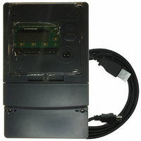
Manufacturer Part Number
MCP3909RD-3PH1
Description
REF DESIGN MCP3909 3PH ENGY MTR
Manufacturer
Microchip Technology
Datasheets
1.MCP3909T-ISS.pdf
(44 pages)
2.MCP3909T-ISS.pdf
(104 pages)
3.MCP3909RD-3PH3.pdf
(88 pages)
Specifications of MCP3909RD-3PH1
Main Purpose
Power Management, Energy/Power Meter
Embedded
No
Utilized Ic / Part
MCP3909, PIC18F2520, PIC18F4550
Primary Attributes
3-Ph, 220 VAC, In Case, LCD, USB, GUI
Secondary Attributes
Opto-Isolated Interface for Safety
Operating Voltage
220 V
Operating Current
5 A
Description/function
Energy Meter
For Use With/related Products
MCP3909
Lead Free Status / RoHS Status
Not applicable / Not applicable


4.4
© 2009 Microchip Technology Inc.
PHASE LAG CALIBRATION
The phase lag calibration function is implemented by the upper computer by sending
the proper commands via the UART. When calibrating phase lag, error from the
calibration equipment and channel information to be adjusted are sent to the dsPIC33F
energy meter. When the front-end receives the command, it calls this module. The flow
is as follows:
1. Determine the phase to be calibrated according to parameters received.
2. Calculate new phase lag calibration coef. according to the error value received
3. Store the coefficient after correction into the EEPROM.
This meter design supports single, two, and five point calibration for phase lag error
correction.
The purpose of phase lag calibration is to eliminate the impact of phase lag introduced
by the current transformer (CT), and voltage transformer (PT) over the power measure-
ment range.
The voltage transformer usually has a constant load, thereby introducing a phase lag
that varies insignificantly. The dynamic range of current is larger, and under different
current loads, phase lags caused by CT vary greatly. In order to meet the requirements
of measurement accuracy in the entire range, it is usually necessary to segment the
phase lag and calibrate.
In this design, current is partitioned into 5 regions.
TABLE 4-1:
The partition limit for the current region can be modified in the header file of the
program. If accuracy is not critical, single-point calibration and two-point calibration can
be used to improve the efficiency of meter calibration.
Single, Two, or Five Point Calibration
Single-, two- or five-point calibration method can be configured by modifying the
header file. When using the single-point calibration, the phase lag compensation
values of all regions are the same; When using two-point calibration, the compensation
values of region 1 and 2 (0-0.075 I
compensation values for region 3, 4 and 5 (0.2 I
4.0 I
and the measured value.
B
) are the same.
Region
1
2
3
4
5
CURRENT REGIONS FOR PHASE CALIBRATION
B
, 0.075 I
B
- 0.2 I
Current Range
0.075 I
0.2 I
0.75 I
1.5 I
B
0 - 0.075 I
- 0.75 I
B
B
B
) are the same, and the phase lag
Meter Calibration
B
- 0.75 I
B
- 4.0 I
-1.5 I
- 0.2 I
B
B
, 0.75 I
B
B
B
B
B
- 1.5 I
DS51723A-page 41
B
, 1.5 I
B
-
Related parts for MCP3909RD-3PH1
Image
Part Number
Description
Manufacturer
Datasheet
Request
R

Part Number:
Description:
BOARD DES MCP3909 ENERGY METER
Manufacturer:
Microchip Technology
Datasheet:

Part Number:
Description:
REF DESIGN FOR MCP3909 W/18F2520
Manufacturer:
Microchip Technology
Datasheet:

Part Number:
Description:
Manufacturer:
Microchip Technology Inc.
Datasheet:
Part Number:
Description:
Manufacturer:
Microchip Technology Inc.
Datasheet:
Part Number:
Description:
Manufacturer:
Microchip Technology Inc.
Datasheet:
Part Number:
Description:
Manufacturer:
Microchip Technology Inc.
Datasheet:
Part Number:
Description:
Manufacturer:
Microchip Technology Inc.
Datasheet:
Part Number:
Description:
Manufacturer:
Microchip Technology Inc.
Datasheet:
Part Number:
Description:
Manufacturer:
Microchip Technology Inc.
Datasheet:
Part Number:
Description:
Manufacturer:
Microchip Technology Inc.
Datasheet: