STEVAL-IAS001V1 STMicroelectronics, STEVAL-IAS001V1 Datasheet
STEVAL-IAS001V1
Specifications of STEVAL-IAS001V1
STEVAL-IAS001V1


Related parts for STEVAL-IAS001V1


STEVAL-IAS001V1 Summary of contents
Page 1
... STM1403. The associated evaluation board (order code STEVAL-IAS001V1) aims to display the capabilities of ST's general purpose microcontroller to fit the market segment of home automation and security, keeping the system cost as low as possible. ...
Page 2
Contents Contents 1 Getting started . . . . . . . . . . . . . . . . . . . . . . . . . . . . . . . . . . . ...
Page 3
UM0408 Appendix D Troubleshooting . . . . . . . . . . . . . . . . . . . . . . . . . . . . . . . . . . . . ...
Page 4
... The version of the Windows OS installed on your PC can be determined by clicking on the System icon in the Control Panel. 1.2 Package contents The keypad controller for the security door evaluation package is orderable with the following order code: STEVAL-IAS001V1. It includes: ● Hardware – One demonstration board ● ...
Page 5
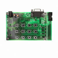
UM0408 Figure 1. Security door keypad controller - front view 3 status LEDs 4x3 key matrix 4 jumpers for physical intrusion configuration The major components present on the front of the board are (see 1. An external power jack for ...
Page 6
Getting started Figure 2. Security door keypad controller - back view Buzzer ST7FLite39 M95080 ST3232C The major components present on the back of the board are (see 1. A buzzer for physical intrusion detection 2. A coin-type battery as back-up ...
Page 7
UM0408 Figure 3. Installation window 2. Click Next to move to the License Agreement window shown in license and if you accept it, click Yes. Figure 4. License agreement 3. The Customer Information window opens as shown in information and ...
Page 8
... Getting started Figure 5. Customer Information 4. Now select the folder in which you want to install the software (see the software is installed to the following path: C:\Program Files\STMicroelectronics\SecurityDoorKeypad Figure 6. Select installation folder 5. After selecting the destination folder, click Next. The software installation then starts, see Figure 7 ...
Page 9
UM0408 Figure 7. Installation process 6. On completion of the installation process, the window shown in the Finish button. Figure 8. Installation complete You will find the software and Help Files have been placed in the installation folder. Also, a ...
Page 10
Running the security door application 2 Running the security door application 2.1 User or standalone mode 2.1.1 Powering on the system This is an easy-to-use system. As soon as you plug in the DC power supply (3.4V to 19V) through ...
Page 11
UM0408 2.1.3 Valid user code A valid user code is 5-digit long. You cannot use "00000" code reserved for the system default setting. A total of 49 user codes are supported by the system. 2.1.4 Door ...
Page 12
Running the security door application 1. Wrong 5-digit user code The user enters a 5-digit user code which does not match any of the valid user codes already added in the system. This event is logged in the EEPROM and ...
Page 13
UM0408 * 1. Press the The red Error LED starts flashing, indicating that you are in administrator mode. 2. Enter the admin password within 1 minute. – If the admin password is valid, the red error LED flashes 6-times. – ...
Page 14
Running the security door application * 1. Press the The red error LED starts flashing, indicating that you are in administrator mode. 2. Enter the admin password, within 1 minute. – If the admin password is valid, the red error ...
Page 15
UM0408 # 1. Press the The red error LED starts to flash, indicating that you are in administrator reset password mode. 2. Enter "12345", within 1 minute. – If correctly entered, the red error LED flashes 6 times. – If ...
Page 16
Running the security door application 2.4.2 Powering on the board This is the same process as with the user mode. Refer to 2.4.3 The first GUI window - login GUI mode Opening the GUI executable, the first window appears as ...
Page 17
UM0408 Figure 14. Communication settings window 2.4.5 Communication error If the following message appears 1. Baud rate mismatch (set it to 4800), the red error LED glows 2. RS232 serial cable not connected properly 3. Incorrect COM port selection Figure ...
Page 18
Running the security door application 2.4.6 Features supported by the GUI Following features are supported by the GUI, 1. Add user code (Actions) Add new user code to the system. 2. Delete user code Delete an existing user code from ...
Page 19
UM0408 2.4.7 Logoff GUI mode After working in administrator mode through the PC GUI, you can choose to log-off (File, Logoff). This sends a disconnect command to the board (see GUI window. Remove the RS232 serial cable. Shortcut: By directly ...
Page 20
Abbreviations Appendix A Abbreviations Table 1. Abbreviations No. 1 RTC EEPROM 4 SPI 5 LED 6 SCI ICC 9 Admin 20/27 Acronym Real Time Clock Personal Computer Electrically Erasable Programmable Read Only Memory Serial ...
Page 21
UM0408 Appendix B Demonstration board schematic VCC TP4 8 13 VCCSW# TP3 7 14 PF1 TP2 15 6 BLD# TP1 Vout G 2 Demonstration board schematic PA1 PA4 PB5 21/27 ...
Page 22
Bill of materials Appendix C Bill of materials Table 2. Bill of materials Reference ST7FLite39F2 MCU U3 1 EEPROM U2 1 Tamper Detect Voltage U1 1 Regulator RS-232 U5 1 interface D4 1 Diode RS-232 J2 ...
Page 23
UM0408 Table 2. Bill of materials Reference Push-button 4 1 Switches Push-button 5 1 Switches Push-button 6 1 Switches Push-button 7 1 Switches Push-button 8 1 Switches Push-button 9 1 Switches Push-button 1 * Switches Push-button # 1 Switches BZ1 ...
Page 24
Bill of materials Table 2. Bill of materials Reference R1, R13, 3 Resistor R14 R10, R12, 4 Resistor R7,R8 C1, C10, C2,C3, 8 Capacitor C4, C7,C8 Capacitor C5 1 Capacitor Power Jack (for J1 1 adaptor) JP1, ...
Page 25
UM0408 Appendix D Troubleshooting D.1 Communication error A "Communication error" message may appear on the PC screen (as in the following reasons: 1. Baud rate mismatch (set it to 4800), signaled by the red error LED glowing 2. RS232 serial ...
Page 26
Revision history 3 Revision history Table 3. Document revision history Date 06-Apr-2007 26/27 Revision 1 Initial release. UM0408 Changes ...
Page 27
... UM0408 Information in this document is provided solely in connection with ST products. STMicroelectronics NV and its subsidiaries (“ST”) reserve the right to make changes, corrections, modifications or improvements, to this document, and the products and services described herein at any time, without notice. All ST products are sold pursuant to ST’s terms and conditions of sale. ...