STEVAL-ISQ002V1 STMicroelectronics, STEVAL-ISQ002V1 Datasheet
STEVAL-ISQ002V1
Specifications of STEVAL-ISQ002V1
Available stocks


Related parts for STEVAL-ISQ002V1


STEVAL-ISQ002V1 Summary of contents
Page 1
Introduction TM The PMBus (power management bus open standard protocol that defines a means of communicating with power conversion and other devices. The PMBus protocol helps to establish the first truly open communications standard for the digital control ...
Page 2
Contents Contents 1 PMBus introduction . . . . . . . . . . . . . . . . . . . . . . . . . . . . . . . . . . . ...
Page 3
AN2511 6.1.3 6.1.4 6.1.5 6.1.6 6.1.7 6.1.8 6.2 Error conditions . . . . . . . . . . . . . . . . . . . . . . . . . . . . . . ...
Page 4
List of tables List of tables Table 1. Operation . . . . . . . . . . . . . . . . . . . . . . . . . . . . . . . ...
Page 5
... Invalid command message . . . . . . . . . . . . . . . . . . . . . . . . . . . . . . . . . . . . . . . . . . . . . . . . . 34 Figure 24. Example of invalid command . . . . . . . . . . . . . . . . . . . . . . . . . . . . . . . . . . . . . . . . . . . . . . . 35 Figure 25. Communication timeout message . . . . . . . . . . . . . . . . . . . . . . . . . . . . . . . . . . . . . . . . . . . 35 Figure 26. Demonstration board schematic . . . . . . . . . . . . . . . . . . . . . . . . . . . . . . . . . . . . . . . . . . . . . 36 Figure 27. Top view layout of the demonstration board . . . . . . . . . . . . . . . . . . . . . . . . . . . . . . . . . . . . 37 Figure 28. Bottom view layout of the demonstration board . . . . . . . . . . . . . . . . . . . . . . . . . . . . . . . . . 37 Figure 29. STEVAL-ISQ002V1 . . . . . . . . . . . . . . . . . . . . . . . . . . . . . . . . . . . . . . . . . . . . . . . . . . . . . . 40 Figure 30. Pin description of RS232 D9 connector . . . . . . . . . . . . . . . . . . . . . . . . . . . . . . . . . . . . . . . 41 Doc ID 13286 Rev 2 List of figures 5/43 ...
Page 6
PMBus introduction 1 PMBus introduction 1.1 PMBus protocol description The PMBus protocol is intended to cover a wide range of power system architectures and converters. PMBus devices must use the system management bus (SMBus), version 1.1. Implemented over the industry-standard ...
Page 7
AN2511 the slave to alert the master whenever it wants to communicate. The control pin is used to switch ON or OFF a PMBus slave. Figure 1. Interface diagram The CONTROL signal is an input signal on a power converter. ...
Page 8
Implementation of PMBus using ST7 I2C 2 Implementation of PMBus using ST7 I 2.1 Firmware architecture This section explains sequence of operation for different software modules. 2 2.1 initialization 2 To use ST7 I C for PMBus communication, ...
Page 9
AN2511 Figure 3. Flowchart: data length calculation Inside both PMBus_CommandRead and PMBus_CommandWrite functions, PMBus_DataLengthCalc is called which calculates the data length based on the command code received. 2.1.3 Read and write operation PMBus master performs read/ write operations with the ...
Page 10
Implementation of PMBus using ST7 I2C Figure 5. Flowchart: write operation START Check if SMBus_Mode for Send Byte command Check if SMBus_Mode for Write Byte command Check if SMBus_Mode for Write Word command Check if SMBus_Mode for Write Block command ...
Page 11
AN2511 3 PMBus commands and source code 3.1 PMBus commands The Part II - command language document of PMBus™ Power System Management Protocol Specification v1.0 provides the list of PMBus commands. This driver supports the following list of commands. For ...
Page 12
PMBus commands and source code Table 4. RESTORE_DEFAULT_ALL Command name Command code Description SMBus transaction type Number of data bytes Table 5. STORE_USER_ALL Command name Command code Description SMBus transaction type Number of data bytes Table 6. VOUT_MODE Command name ...
Page 13
AN2511 Table 7. VOUT_COMMAND Command name Command code Description SMBus transaction type Number of data bytes Table 8. VOUT_MAX Command name Command code Description SMBus transaction type Number of data bytes Table 9. VOUT_MARGIN_HIGH Command name Command code Description SMBus ...
Page 14
PMBus commands and source code Table 11. VOUT_OV_WARN_LIMIT (continued) Description SMBus transaction type Number of data bytes Table 12. VOUT_UV_WARN_LIMIT Command name Command code Description SMBus transaction type Number of data bytes Table 13. IOUT_OC_FAULT_LIMIT Command name Command code Description ...
Page 15
AN2511 Table 15. OT_FAULT_LIMIT (continued) SMBus transaction type Number of data bytes Table 16. OT_FAULT_RESPONSE Command name Command code Description SMBus transaction type Number of data bytes Table 17. OT_WARN_LIMIT Command name Command code Description SMBus transaction type Number of ...
Page 16
PMBus commands and source code Table 20. TOFF_DELAY (continued) Description SMBus transaction type Number of data bytes Table 21. TOFF_FALL Command name Command code Description SMBus transaction type Number of data bytes Table 22. STATUS_BYTE Command name Command code Description ...
Page 17
AN2511 Table 24. STATUS_VOUT (continued) SMBus transaction type Number of data bytes Table 25. STATUS_IOUT Command name Command code Description SMBus transaction type Number of data bytes Table 26. STATUS_TEMPERATURE Command name Command code Description SMBus transaction type Number of ...
Page 18
PMBus commands and source code Table 27. STATUS_MFR_SPECIFIC Command name Command code Description SMBus transaction type Number of data bytes Table 28. READ_VOUT Command name Command code Description SMBus transaction type Number of data bytes Table 29. READ_IOUT Command name ...
Page 19
AN2511 Table 31. PMBUS_REVISION Command name Command code Description SMBus transaction type Number of data bytes Table 32. MFR_ID Command name Command code Description SMBus transaction type Number of data bytes Table 33. MFR_MODEL Command name Command code Description SMBus ...
Page 20
PMBus commands and source code Table 35. MFR_LOCATION Command name Command code Description SMBus transaction type Number of data bytes Table 36. MFR_DATE Command name Command code Description SMBus transaction type Number of data bytes Table 37. MFR_SERIAL Command name ...
Page 21
AN2511 Table 39. MFR_SPECIFIC_01 Command name Command code Description SMBus transaction type Number of data bytes Table 40. MFR_SPECIFIC_02 Command name Command code Description SMBus transaction type Number of data bytes 3.2 Source code The source code is attached in ...
Page 22
... Source File Name : Main.c Group Author Date First Issued: 01/09/2006 -*-*-*-*-*-*-*-*-*-*-*-*-*-*-*-*-*-*-*-*-*-*-*-*-*-*-*-*-*-*-*-*-*-*-*-*-*-*-*- THE SOFTWARE INCLUDED IN THIS FILE IS FOR GUIDANCE ONLY. STMicroelectronics SHALL NOT BE HELD LIABLE FOR ANY DIRECT, INDIRECT OR CONSEQUENTIAL DAMAGES WITH RESPECT TO ANY CLAIMS ARISING FROM USE OF THIS SOFTWARE. -*-*-*-*-*-*-*-*-*-*-*-*-*-*-*-*-*-*-*-*-*-*-*-*-*-*-*-*-*-*-*-*-*-*-*-*-*-*-*- ********************************Documentation********************************** General Purpose - Contains main source code. In this file, the PMBus command files are written ...
Page 23
AN2511 PCOR = CONTROL ; PCDR = CONTROL ; /*----------------------- Alert Interrupt configuration --------------------- ----------*/ EnableInterrupts; MISCR1 = 0x10 ; /*---------------------PMBus communication configuration-------------------*/ while ( I2C configuration: ST7 I2C address 0x30, communication speed 100kHz */ PMBus_Init (SMBs_MISC, SLAVEADD, ...
Page 24
PMBus interfacing results 4 PMBus interfacing results This section describes the results of interfacing the demonstration board with Artesyn and SiLabs modules. 4.1 Interfacing with Artesyn module The following table shows the different PMBus commands and ST demonstration board results ...
Page 25
AN2511 Table 41. PMBus interfacing with Artesyn module: results (continued) Command PMBus command code 78 STATUS_BYTE 79 STATUS_WORD 7A STATUS_VOUT 7B STATUS_IOUT STATUS_TEMPERATU 7D RE STATUS_MFR_SPECI 80 FIC 8B READ_VOUT 8C READ_IOUT 8D READ_TEMPERATURE 98 PMBUS_REVISION 99 MFR_ID 9A MFR_MODEL ...
Page 26
PMBus interfacing results Table 42. PMBus interfacing with SiLabs module: results (continued) Command code 03 CLEAR_FAULTS 12 RESTORE_DEFAULT_ALL 15 STORE_USER_ALL 20 VOUT_MODE 21 VOUT_COMMAND 24 VOUT_MAX 25 VOUT_MARGIN_HIGH 25 VOUT_MARGIN_HIGH 26 VOUT_MARGIN_LOW 42 VOUT_OV_WARN_LIMIT 43 VOUT_UV_WARN_LIMIT 4F OT_FAULT_LIMIT 50 OT_FAULT_RESPONSE ...
Page 27
AN2511 5 PMBus demonstration board To show the features of the ST7 I available on request. Please contact the nearest ST office to get this board. The evaluation board has an ST72F264G1 MCU that has 4 KBytes Flash memory. All ...
Page 28
PMBus demonstration board Figure 7. Baud rate configuration 4. Configure the following settings in hyperterminal: File -> Properties -> Settings -> ASCII setup Figure 8. Hyperterminal settings - ASCII setup configuration 5. Press call in hyperterminal to establish a connection ...
Page 29
AN2511 runs using the resonator clock (16 MHz). If the jumper is connected between pins 2 and 3 then the application is stopped and ST7 MCU can be re-programmed. d) JP4: JP4 is used to select the power supply as ...
Page 30
Using the demonstration board 6 Using the demonstration board After installing the setup as explained in hyperterminal. Figure 9. Hyperterminal message to show company name and selection of communication speed If there is any problem in getting the message, press ...
Page 31
AN2511 Figure 11. Slave address entry message If the user enters a wrong slave address then one of the following error messages shown in Figure 12 or Figure 13 Figure 12. Wrong slave address entry - response 1 Figure 13. ...
Page 32
Using the demonstration board 6.1.6 Continuous read mode The user can press 0 to read all PMBus commands. The lists of supported commands are shown in the following figure. Figure 16. Continuous read operation Command codes 0xD0, 0xD1 and 0xD2 ...
Page 33
AN2511 For example, to enter a date as “15 -12-1991”, then data should be entered as 313531323931 (where 31h=ASCII ”1”, 35h=ASCII “5”, etc., and the date will read “151291”). An example of this operation is shown below. Figure 19. Write ...
Page 34
Using the demonstration board Figure 21. Group command code entry message from hyperterminal An example of this operation is shown below. Figure 22. Group command operation example 6.2 Error conditions The following error conditions may be encountered during PMBus communication. ...
Page 35
AN2511 Figure 24. Example of invalid command 6.2.2 Communication timeout This error appears when the PMBus communication fails due to one of the following reasons: ● The slave device doesn’t acknowledge the master ● The clock low interval exceeds the ...
Page 36
Hardware description 7 Hardware description This section provides schematics, BOM (bill of materials), layout and picture of the demonstration board. 7.1 Schematic and layout The following figures show the schematic and layouts of the demonstration board. Figure 26. Demonstration board ...
Page 37
AN2511 Figure 27. Top view layout of the demonstration board Figure 28. Bottom view layout of the demonstration board Doc ID 13286 Rev 2 Hardware description 37/43 ...
Page 38
... CON2 SIP-2 CON3 SIP-3 CON4 SIP-4 CON7 SIP-7 DB9 DB9/F 16 MHz (KDS) XTAL-1 ICC IDC-10B JACK TAP_2.5 mm L7805CD2T-TR TO-220 STMicroelectronics SMD LED LED-SMD Manufacturer’s ordering code / Supplier orderable part number Any Any Any Any Any Any Any Any Any Any ...
Page 39
... MCU U2 RS232 level translator: U3 Switch S1 Diode: D2 ZENER diode: ZD1 Value / generic part Package Manufacturer number ST72F264G1M6 SOL-28 STMicroelectronics ST3232CTR SO-16 STMicroelectronics TACT SWITCH PUSH-4 1N5817 DO41 STMicroelectronics SMAJ TO220 STMicroelectronics Manufacturer’s ordering code / Supplier orderable part number ST72F264G1M6 ST3232CTR Any ...
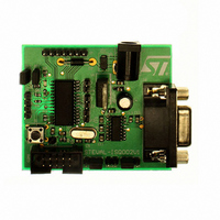
Page 40
... Hardware description 7.3 Demonstration board photo The following figure shows the picture of the demonstration board. Figure 29. STEVAL-ISQ002V1 40/43 Doc ID 13286 Rev 2 AN2511 ...
Page 41
AN2511 Appendix A Configuration A.1 RS232 configuration The following figure shows the pin description of the RS232 D9 connector. Figure 30. Pin description of RS232 D9 connector Doc ID 13286 Rev 2 Configuration 41/43 ...
Page 42
Revision history Revision history Table 44. Document revision history Date 17-Apr-2007 25-Aug-2010 42/43 Revision 1 Initial release. – Modified: Figure 9, 10, 16, 17, 18, 19, 20, 23, 24, 25, 26, 29, Table 43 2 – Added: Figure 27, – ...
Page 43
... AN2511 Information in this document is provided solely in connection with ST products. STMicroelectronics NV and its subsidiaries (“ST”) reserve the right to make changes, corrections, modifications or improvements, to this document, and the products and services described herein at any time, without notice. All ST products are sold pursuant to ST’s terms and conditions of sale. ...