STEVAL-IHM010V1 STMicroelectronics, STEVAL-IHM010V1 Datasheet - Page 24
STEVAL-IHM010V1
Manufacturer Part Number
STEVAL-IHM010V1
Description
KIT IGBT PWR MODULE CTRL ST7MC
Manufacturer
STMicroelectronics
Type
Motor / Motion Controllers & Driversr
Specifications of STEVAL-IHM010V1
Main Purpose
Power Management, Motor Control
Embedded
Yes, MCU, 8-Bit
Utilized Ic / Part
ST7FMC2S4
Primary Attributes
3-Ph Brushless BLDC, AC & 3-Ph AC Induction (ACIM) Motors
Secondary Attributes
Graphic User Interface, 4 Pots for Runtime Settings, Start/Stop and Reset Buttons
Input Voltage
5 V
Product
Power Management Modules
Silicon Manufacturer
ST Micro
Core Architecture
ARM
Core Sub-architecture
ARM7TDMI
Silicon Core Number
ST7
Silicon Family Name
ST7MCx
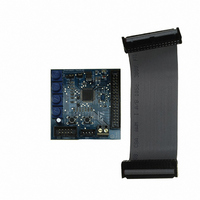
Kit Contents
Board
Lead Free Status / RoHS Status
Lead free / RoHS Compliant
For Use With/related Products
ST7MC
Other names
497-8400


Motor control demonstration
Table 6.
24/48
Proportional coefficient
Integral coefficient (Ki)
Generate source files
before auto-switched
Number of Z events
Change motor type
Advanced settings
B-emf falling edge
Current reference
Current reference
B-emf rising edge
Parameter name
Delay coefficient
From RV2-RV3
Sampling time
Target speed
Duty cycle
Duty cycle
From RV1
Maximum
Minimum
mode
(KP)
"3 Phase BLAC/DC (trapezoidal)" basic parameters (continued)
the number of consecutive Z events that occur before the microcontroller runs the motor in
the RV2 potentiometer and the value of Falling Delay is defined by the RV3 potentiometer.
the “change motor type” button enables the user to change the motor type (see
The value of current flowing inside one (of three) phases of the motor at run time in “open
When the “From RV2 - RV3” checkbox is selected, the value of Rising Delay is defined by
the “generate source files” button enables the user to generate the configuration “.h” files
directory in the firmware working folder (see
the target mechanical (rotor) speed in RPMs (or Hz) if speed regulation is set to “closed
the value of current flowing inside one (of three) phases of the motor at the end of the
shown in
the “advanced settings” button enables the user to set the advanced parameters (see
user can select in which folder to create the file. User must choose the right “source”
the value of the Integral Coefficient (Ki) of the Proportional Integrative (PI) regulator
Current reference is defined by the RV1 potentiometer (only for current mode), or
Duty cycle value is defined by the RV1 potentiometer (only for voltage mode), or
loop” (alternate between RPM and Hz settings by clicking on the “RPM” button)
the Duty cycle percentage when the motor is run in “open loop” “voltage mode”
Closed loop parameter (only in closed loop)
Target speed is defined by the RV1 potentiometer (only for closed loop)
the duty cycle percentage during the Ramp Up (only in voltage mode)
Section 7.4.5: "3 Phase BLAC/DC (trapezoidal)" advanced
If this box is unchecked, the above parameters are set by the user.
If this box is unchecked, the above parameters are set by the user.
Table 5
the maximum target rotor frequency in closed loop, express in Hz
the minimum target rotor frequency in closed loop, express in Hz
the value of the Proportional Coefficient (Kp) of the PI regulator
the B-EMF falling edge delay coefficient value (from 0 to 255)
the B-EMF rising edge delay coefficient value (from 0 to 255)
- Configuration ".h" files. A “save” dialog window appears, where the
Electrical frequency
the regulation sampling time (in milliseconds)
when the “From RV1” checkbox is selected:
“acceleration phase” (only in current mode)
Run settings
loop” “current mode”
autoswitched mode
Description
Section 7.4.1: Choosing the right
settings)
firmware).
Figure
UM0430
10)
Related parts for STEVAL-IHM010V1
Image
Part Number
Description
Manufacturer
Datasheet
Request
R

Part Number:
Description:
BOARD EVAL FOR MEMS SENSORS
Manufacturer:
STMicroelectronics
Datasheet:

Part Number:
Description:
KIT DEV STARTER ST10F276Z5
Manufacturer:
STMicroelectronics
Datasheet:

Part Number:
Description:
BOARD EVAL HDMI $ VIDEO SWITCH
Manufacturer:
STMicroelectronics
Datasheet:

Part Number:
Description:
BOARD DEMO ACCELEROMETER DIL24
Manufacturer:
STMicroelectronics
Datasheet:

Part Number:
Description:
BOARD STLM75/STDS75/ST72F651
Manufacturer:
STMicroelectronics
Datasheet:

Part Number:
Description:
EVAL BOARD 3AXIS MEMS ACCELLRMTR
Manufacturer:
STMicroelectronics
Datasheet:

Part Number:
Description:
BOARD EVAL 8BIT MICRO + TDE1708
Manufacturer:
STMicroelectronics
Datasheet:

Part Number:
Description:
EVAL BOARD A/D TS4657
Manufacturer:
STMicroelectronics
Datasheet:

Part Number:
Description:
BOARD ADAPTER 20DIP LIS3LV02DL
Manufacturer:
STMicroelectronics
Datasheet:

Part Number:
Description:
BOARD DEMO STM8S207R6/LIS331DLH
Manufacturer:
STMicroelectronics
Datasheet:

Part Number:
Description:
STMicroelectronics [RIPPLE-CARRY BINARY COUNTER/DIVIDERS]
Manufacturer:
STMicroelectronics
Datasheet:
Part Number:
Description:
STMicroelectronics [LIQUID-CRYSTAL DISPLAY DRIVERS]
Manufacturer:
STMicroelectronics
Datasheet:
Part Number:
Description:
BOARD EVAL FOR MEMS SENSORS
Manufacturer:
STMicroelectronics
Datasheet: