NCP1271ADAPGEVB ON Semiconductor, NCP1271ADAPGEVB Datasheet - Page 15
NCP1271ADAPGEVB
Manufacturer Part Number
NCP1271ADAPGEVB
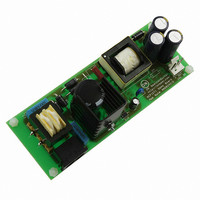
Description
EVAL BOARD FOR NCP1271ADAPG
Manufacturer
ON Semiconductor
Datasheets
1.NCP1271P100G.pdf
(21 pages)
2.NCP1271ADAPGEVB.pdf
(1 pages)
3.NCP1271ADAPGEVB.pdf
(10 pages)
Specifications of NCP1271ADAPGEVB
Design Resources
NCP1271 Adapter EVB BOM NCP1271ADAPGEVB Gerber Files NCP1271EVB Schematic
Main Purpose
AC/DC, Primary Side
Outputs And Type
1, Isolated
Voltage - Output
19V
Current - Output
3A
Voltage - Input
85 ~ 265VAC
Regulator Topology
Flyback
Frequency - Switching
65kHz
Board Type
Fully Populated
Utilized Ic / Part
NCP1271
Silicon Manufacturer
On Semiconductor
Silicon Core Number
NCP1271
Kit Application Type
Power Management
Application Sub Type
PWM Controller
Peak Reflow Compatible (260 C)
No
Rohs Compliant
No
Lead Free Status / RoHS Status
Lead free / RoHS Compliant
Power - Output
-
Lead Free Status / Rohs Status
Lead free / RoHS Compliant
Other names
NCP1271ADAPGEVBOS


also enters fault condition when V
(9.1 V typical). The device will again enter a double hiccup
mode and try to restart the application.
Operation in Standby Condition
load, the duty cycle on the controller can become very
small. At this point, a significant portion of the power
dissipation is related to the power MOSFET switching on
and off. To reduce this power dissipation, the NCP1271
“skips” pulses when the FB level (i.e. duty cycle) drops too
low. The level that this occurs at is completely adjustable
by setting a resistor on pin 1.
and the FB voltage rises. When the FB voltage rises above
the V
minimize the risk of acoustic noise, when the drive turns
back on the duty cycle of its pulses are also ramped up. This
is similar to the soft start function, except the period of the
Soft−Skip operation is only 300 ms instead of 4.0 ms for the
soft start function. This feature produces a timing diagram
shown in Figure 36.
Table 1. Skip Resistor R
Besides the timer−based fault detection, the NCP1271
During standby operation, or when the output has a light
By discontinuing pulses, the output voltage slowly drops
skip
%Ics
100%
level, the drive is turned back on. However, to
12%
25%
40%
50%
V
0%
skip
FB
skip
Figure 36. Soft−Skip Operation
I D
skip
V
Range for D
skip
0.375 V
0.75 V
1.2 V
1.5 V
3.0 V
0 V
or V
CC
drops below V
pin1
Soft Skip
max
= 80% and I
http://onsemi.com
CC
(off
17.4 kW
34.8 kW
8.7 kW
28 kW
70 kW
R
)
0 W
skip
skip
15
= 43 mA
Skip Duty Cycle
maximum peak current at which the controller enters skip
mode. Ics
by equation 5. However, the higher that %Ics
greater the drain current when skip is entered. This
increases the risk of acoustic noise. Conversely, the lower
that %Ics
expended turning the switch on and off. Therefore it is
important to adjust %Ics
application.
Skip Adjustment
skip level is 1.2 V (V
40% Ics
Therefore, the controller will enter skip mode when the
peak current is less than 40% of the maximum peak current.
However, this level can be externally adjusted by placing
a resistor R
(Pin 4). The level will change according to equation 6.
0 V and 3.0 V. Therefore, R
given in Table 1.
Skip peak current, %Ics
By default, when the Skip/latch Pin (Pin 1) is opened, the
To operate in skip cycle mode, V
skip
skip
skip
Never skips.
−
−
−
−
Always skips.
skip
(%Ics
can be any value from 0 to 100% as defined
is the larger the percentage of energy is
% Ics skip +
between skip/latch pin (Pin 1) and Ground
V skip + R skip
skip
skip
= 1.2 V / 3.0 V
skip
= 1.2 V). This corresponds to a
skip
to the optimal level for a given
V skip
Comment
skip
3 V
, is the percentage of the
must be within the levels
· 100%
I skip
skip
must be between
100% = 40%).
skip
(eq. 5)
(eq. 6)
is, the
Related parts for NCP1271ADAPGEVB
Image
Part Number
Description
Manufacturer
Datasheet
Request
R

Part Number:
Description:
ON Semiconductor [VOLTAGE REGULATOR]
Manufacturer:
ON Semiconductor
Datasheet:
Part Number:
Description:
357-036-542-201 CARDEDGE 36POS DL .156 BLK LOPRO
Manufacturer:
ON Semiconductor
Datasheet:
Part Number:
Description:
357-036-542-201 CARDEDGE 36POS DL .156 BLK LOPRO
Manufacturer:
ON Semiconductor
Datasheet:
Part Number:
Description:
357-036-542-201 CARDEDGE 36POS DL .156 BLK LOPRO
Manufacturer:
ON Semiconductor
Datasheet:
Part Number:
Description:
357-036-542-201 CARDEDGE 36POS DL .156 BLK LOPRO
Manufacturer:
ON Semiconductor
Datasheet:
Part Number:
Description:
357-036-542-201 CARDEDGE 36POS DL .156 BLK LOPRO
Manufacturer:
ON Semiconductor
Datasheet:
Part Number:
Description:
357-036-542-201 CARDEDGE 36POS DL .156 BLK LOPRO
Manufacturer:
ON Semiconductor
Datasheet:
Part Number:
Description:
357-036-542-201 CARDEDGE 36POS DL .156 BLK LOPRO
Manufacturer:
ON Semiconductor
Datasheet:
Part Number:
Description:
357-036-542-201 CARDEDGE 36POS DL .156 BLK LOPRO
Manufacturer:
ON Semiconductor
Datasheet:
Part Number:
Description:
357-036-542-201 CARDEDGE 36POS DL .156 BLK LOPRO
Manufacturer:
ON Semiconductor
Datasheet:
Part Number:
Description:
357-036-542-201 CARDEDGE 36POS DL .156 BLK LOPRO
Manufacturer:
ON Semiconductor
Datasheet:
Part Number:
Description:
Manufacturer:
ON Semiconductor
Datasheet:
Part Number:
Description:
Manufacturer:
ON Semiconductor
Datasheet:
Part Number:
Description:
Manufacturer:
ON Semiconductor
Datasheet: