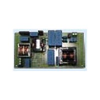
EVL130W-STRLIG STMicroelectronics, EVL130W-STRLIG Datasheet - Page 17

EVL130W-STRLIG
Manufacturer Part Number
EVL130W-STRLIG
Description
BOARD EVAL L6562AT L6599AT
Manufacturer
STMicroelectronics
Specifications of EVL130W-STRLIG
Current - Output / Channel
2.7A
Outputs And Type
1, Isolated
Voltage - Output
48V
Features
EN55022 class B compliant
Voltage - Input
85 ~ 305 V
Utilized Ic / Part
L6562AT, L6599AT
Description/function
SMPS for LED Street Lighting Applications
Data Bus Width
4 bit
Maximum Clock Frequency
30 MHz
Maximum Power Dissipation
130 W
Operating Supply Voltage
85 V to 305 V
Operating Voltage
48 V
Product
Display Modules
Lead Free Status / RoHS Status
Lead free / RoHS Compliant
For Use With/related Products
L6562AT, L6599AT
Other names
497-10541
Available stocks
Company
Part Number
Manufacturer
Quantity
Price
AN3106
4.3
Figure 23. EVL130W-STRLIG demonstration
CH1: PWM dimming signal
CH4: SMPS output current
Dynamic load operation
The waveforms shown in
the operation of supplying converters dedicated to power LED strips with constant current.
In both figures it is possible to see the output voltage modulation during operation with
variable load due to the dimming of the LED current by PWM. For both measurements, the
dimming frequency has been chosen at 300 Hz, a typical value for dimming.
In
thus very close to the converter’s nominal output power. The output voltage has two
modulations. One is due to the rejection of the PFC output voltage ripple already measured
in
The peak-to-peak variation is 5.37 V but it doesn't present any problem for the load since the
converters reject the modulation.
In
current was 3 A and the dimming duty cycle was 15%, for an output power of 21 W. Even in
this case, the peak-to peak modulation doesn't present any issue for the downstream
current regulators and the board still works correctly.
Please note that for correct operation with LED strips, the board needs additional capacitors
connected on the +48 V output bus. The board has not been equipped with all of the
capacitors necessary for correct operation with LEDs, but only with minimum capacitance to
allow board operation in order to optimize the system cost and reliability. The additional
capacitors needed are intended to be placed close to each LED strip current regulator, thus
filtering the EMI generated by these. In several cases, in fact, the power supply is placed at
the base of the lighting pole while the LED current regulators are located on top, in the lamp.
The long connection wiring between the power supply and the converters can act as an
antenna radiating EMI. Thus local filtering minimizes the radiated EMI.
board: output voltage variation
driving a CC LED converter -
PWM = 90%
Figure 22
Figure 23
Figure 24
where the voltage variation due to the LED current dimming is superimposed.
the converter’s output current was 2.6 A and the dimming duty cycle was 90%,
instead the converter has been checked at light load, so the peak output
CH2: V
OUT
Figure 23
Doc ID 16775 Rev 1
and
Figure 24
Figure 24. EVL130W-STRLIG demonstration
CH1: PWM dimming signal
CH4: SMPS output current
pertain to the demonstration board during
board: output voltage variation
driving a CC LED converter -
PWM = 15%
CH2: V
OUT
Functional check
17/35


