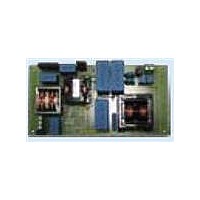
EVL130W-STRLIG STMicroelectronics, EVL130W-STRLIG Datasheet - Page 19

EVL130W-STRLIG
Manufacturer Part Number
EVL130W-STRLIG
Description
BOARD EVAL L6562AT L6599AT
Manufacturer
STMicroelectronics
Specifications of EVL130W-STRLIG
Current - Output / Channel
2.7A
Outputs And Type
1, Isolated
Voltage - Output
48V
Features
EN55022 class B compliant
Voltage - Input
85 ~ 305 V
Utilized Ic / Part
L6562AT, L6599AT
Description/function
SMPS for LED Street Lighting Applications
Data Bus Width
4 bit
Maximum Clock Frequency
30 MHz
Maximum Power Dissipation
130 W
Operating Supply Voltage
85 V to 305 V
Operating Voltage
48 V
Product
Display Modules
Lead Free Status / RoHS Status
Lead free / RoHS Compliant
For Use With/related Products
L6562AT, L6599AT
Other names
497-10541
Available stocks
Company
Part Number
Manufacturer
Quantity
Price
AN3106
4.5
Figure 25. EVL130W-STRLIG demonstration
CH1: V_OUT_PFC
CH3: DELAY pin
Figure 25
of the board during short-circuit operation. Thanks to the narrow operating time with respect
to the off-time, the average output current as well as the average primary current are limited.
This will avoid converter overheating and consequent failures. Removing the short allows
the board to resume normal operation.
Figure 26
the LLC stage. The open loop operation provides an increase also of the auxiliary voltage
that will trigger the L6599AT pin #9 (DIS) protection pin via the Zener diode D17. As
a consequence, the L6599AT will shut down, stopping the operation. The L6599AT will
activate also the PFC_STOP pin (#9) that will stop the PFC too, thus both controllers will no
longer be powered by V
a new startup cycle will take place. This sequence continues until the open loop is removed.
Converter startup
Figure 27
begins operation in ~300 ms, while at 230 V
needed to charge the V
switching and the PFC output voltage starts increasing. Once the PFC output voltage
reaches the enable level set via the L6599AT LINE pin, even the LLC stage starts switching
and the output voltage rises up to the nominal level. The V
coil charge pump, and then once the L6599AT starts operating, the V
the LLC transformer auxiliary winding. The details of converter sequencing can be found in
Figure 28
board: short-circuit at 115 V
- 60 Hz - full load
shows the operation of the DELAY pin and the consequent hiccup mode operation
shows the operation of the demonstration board during “open loop” operation by
and
and
CH2: HB voltage
CH4: U1 pin INV
Figure 29
Figure
30.
CC
CC
show the converter startup. We note that at 115 V
. Once V
to the L6562AT turn-on voltage. Thus the L6562AT starts
AC
Doc ID 16775 Rev 1
CC
drops below the UVLO, the latch is removed and then
Figure 26. EVL130W-STRLIG demonstration
CH1: Q1_Drain
CH3: V
AC
OUT
it takes around 150 ms. This is the time
board: open loop at 115 V
- 65 W load
CC
is initially supplied by the PFC
CH2: HB voltage
CH4: DIS pin
CC
is also provided by
Functional check
AC
the converter
AC
- 60 Hz
19/35


