EVL130W-STRLIG STMicroelectronics, EVL130W-STRLIG Datasheet - Page 7
EVL130W-STRLIG
Manufacturer Part Number
EVL130W-STRLIG
Description
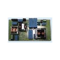
BOARD EVAL L6562AT L6599AT
Manufacturer
STMicroelectronics
Specifications of EVL130W-STRLIG
Current - Output / Channel
2.7A
Outputs And Type
1, Isolated
Voltage - Output
48V
Features
EN55022 class B compliant
Voltage - Input
85 ~ 305 V
Utilized Ic / Part
L6562AT, L6599AT
Description/function
SMPS for LED Street Lighting Applications
Data Bus Width
4 bit
Maximum Clock Frequency
30 MHz
Maximum Power Dissipation
130 W
Operating Supply Voltage
85 V to 305 V
Operating Voltage
48 V
Product
Display Modules
Lead Free Status / RoHS Status
Lead free / RoHS Compliant
For Use With/related Products
L6562AT, L6599AT
Other names
497-10541
Available stocks
Company
Part Number
Manufacturer
Quantity
Price


AN3106
1.2
1.3
1.4
Resonant power stage
The downstream converter is a resonant LLC half-bridge stage working with 50 percent
fixed duty cycle and variable frequency. It implements the ST L6599AT, integrating all
functions necessary to properly control the resonant topology.
The resonant transformer, manufactured by MAGNETICA, uses the integrated magnetic
approach, so the leakage inductance is used for resonant operation of the circuit. Thus, no
external, additional coil is needed for the resonance. The transformer secondary winding
configuration is the typical center tap, using a couple of power Schottky rectifiers type
STPS10150CG. The output capacitors are film type, 4.7 µF - 63 V from EPCOS. As for the
PFC stage, using film capacitors allows considerably increasing the MTBF of the board.
A small LC filter has been added on the output, in order to filter the high-frequency ripple.
D21, D22, R55 constitute a voltage-controlled bleeder. In case of no-load operation of the
SMPS, this circuit provides a bleeder limiting the output voltage from increasing, but not
affecting the efficiency during normal operation. Please note that the converter has not been
designed to work in this condition and therefore its mains consumption is not optimized
(~3 W).
Startup sequence
The PFC acts as master and therefore starts first. The resonant stage operates only if the
PFC is delivering the nominal output voltage to prevent the resonant converter from working
with an insufficient input voltage that can cause incorrect capacitive mode operation. Thus,
both stages are designed to work according to this sequence.
For correct sequencing the L6599AT makes use of the LINE pin (#7) to sense the PFC
output voltage via a resistor divider. The L6599AT LINE pin (#7) has an internal comparator
which has a hysteresis allowing to set independently the turn-on and turn-off voltage. At
startup the LLC stage starts once the PFC output voltage reaches ~ 430 V, while the turn-off
threshold has been set to ~330 V.
Output voltage feedback loop
The output voltage is kept stable by means of a feedback loop implementing a typical circuit
using a TS2431 modulating the current in the optocoupler diode.
On the primary side, R43 - connecting pin RF
allows modulating the L6599AT oscillator frequency, thus keeping the output voltage
regulated. It also sets the maximum switching frequency at about 130 kHz. R42, that
connects the same pin to ground, sets the minimum switching frequency. The R-C series
R37 and C24 sets both soft-start maximum frequency and duration.
Doc ID 16775 Rev 1
Main characteristics and circuit description
MIN
(#4) to the optocoupler's phototransistor -
7/35
Related parts for EVL130W-STRLIG
Image
Part Number
Description
Manufacturer
Datasheet
Request
R

Part Number:
Description:
BOARD EVAL L6562AT L6599AT
Manufacturer:
STMicroelectronics
Datasheet:
Part Number:
Description:
STMicroelectronics [RIPPLE-CARRY BINARY COUNTER/DIVIDERS]
Manufacturer:
STMicroelectronics
Datasheet:
Part Number:
Description:
STMicroelectronics [LIQUID-CRYSTAL DISPLAY DRIVERS]
Manufacturer:
STMicroelectronics
Datasheet:

Part Number:
Description:
BOARD EVAL FOR MEMS SENSORS
Manufacturer:
STMicroelectronics
Datasheet:
Part Number:
Description:
NPN TRANSISTOR POWER MODULE
Manufacturer:
STMicroelectronics
Datasheet:
Part Number:
Description:
TURBOSWITCH ULTRA-FAST HIGH VOLTAGE DIODE
Manufacturer:
STMicroelectronics
Datasheet:
Part Number:
Description:
Manufacturer:
STMicroelectronics
Datasheet:
Part Number:
Description:
DIODE / SCR MODULE
Manufacturer:
STMicroelectronics
Datasheet:
Part Number:
Description:
DIODE / SCR MODULE
Manufacturer:
STMicroelectronics
Datasheet:
Part Number:
Description:
Search -----> STE16N100
Manufacturer:
STMicroelectronics
Datasheet:
Part Number:
Description:
Search ---> STE53NA50
Manufacturer:
STMicroelectronics
Datasheet:
Part Number:
Description:
NPN Transistor Power Module
Manufacturer:
STMicroelectronics
Datasheet: