EVL130W-STRLIG STMicroelectronics, EVL130W-STRLIG Datasheet - Page 18
EVL130W-STRLIG
Manufacturer Part Number
EVL130W-STRLIG
Description
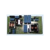
BOARD EVAL L6562AT L6599AT
Manufacturer
STMicroelectronics
Specifications of EVL130W-STRLIG
Current - Output / Channel
2.7A
Outputs And Type
1, Isolated
Voltage - Output
48V
Features
EN55022 class B compliant
Voltage - Input
85 ~ 305 V
Utilized Ic / Part
L6562AT, L6599AT
Description/function
SMPS for LED Street Lighting Applications
Data Bus Width
4 bit
Maximum Clock Frequency
30 MHz
Maximum Power Dissipation
130 W
Operating Supply Voltage
85 V to 305 V
Operating Voltage
48 V
Product
Display Modules
Lead Free Status / RoHS Status
Lead free / RoHS Compliant
For Use With/related Products
L6562AT, L6599AT
Other names
497-10541
Available stocks
Company
Part Number
Manufacturer
Quantity
Price


Functional check
4.4
18/35
The capacitance to be added to the 48 V bus for correct operation with LEDs is around
40 µF. In order to not affect the board MTBF, we suggest using the same type of capacitors
already used on the power supply board.
Overcurrent and overvoltage protection
The L6599AT is equipped with a current sensing input (pin #6, ISEN) and a dedicated
overcurrent management system. The current flowing in the resonant tank is detected and
the signal is fed into the ISEN pin. It is internally connected to a first comparator, referenced
to 0.8 V, and to a second comparator referenced to 1.5 V. If the voltage externally applied to
the pin exceeds 0.8 V, the first comparator is tripped, causing an internal switch to be turned
on and discharging the soft-start capacitor C24 (CSS).
Under output short-circuit, this operation results in a nearly constant peak primary current.
With the L6599AT the designer can program externally the maximum time that the converter
is allowed to run overloaded or under short-circuit conditions. Overloads or short-circuits
lasting less than the set time will not cause any other action, hence providing the system
with immunity to short duration phenomena. If, instead, the overload condition persists,
a protection procedure is activated that shuts down the L6599AT. In case of continuous
overload or short-circuit, it will result in continuous intermittent operation with a user-defined
duty cycle.
This function is implemented with the DELAY pin (#2), by means of a capacitor C21 and the
parallel resistor R32 connected to ground. As the voltage on the ISEN pin exceeds 0.8 V, the
first OCP comparator, in addition to discharging CSS, turns on an internal 150 µA current
generator that via the DELAY pin charges C21. As the voltage on C21 is 3.5 V, the L6599AT
stops switching and the PFC_STOP pin (#9) is pulled low, turning off also the PFC stage via
the L6562AT pin#1 (INV). The internal generator is also turned off, so that C21 will now be
slowly discharged by R32. The IC will restart once the voltage on C21 is less than 0.3 V.
Additionally, if the voltage on the ISEN pin reaches 1.5 V for any reason (e.g. transformer
saturation), the second comparator will be triggered, the L6599AT will shut down and the
operation will be resumed after recycling of the V
intervention of the second level comparator will latch the operation of the L6599AT and the
PFC_STOP pin (#9) will stop the PFC. Both controllers will no longer be powered by V
and the latch will be removed and then a new startup cycle will take place. This sequence
continues until the short is removed.
Doc ID 16775 Rev 1
CC
. In this demonstration board the
AN3106
CC
Related parts for EVL130W-STRLIG
Image
Part Number
Description
Manufacturer
Datasheet
Request
R

Part Number:
Description:
BOARD EVAL L6562AT L6599AT
Manufacturer:
STMicroelectronics
Datasheet:
Part Number:
Description:
STMicroelectronics [RIPPLE-CARRY BINARY COUNTER/DIVIDERS]
Manufacturer:
STMicroelectronics
Datasheet:
Part Number:
Description:
STMicroelectronics [LIQUID-CRYSTAL DISPLAY DRIVERS]
Manufacturer:
STMicroelectronics
Datasheet:

Part Number:
Description:
BOARD EVAL FOR MEMS SENSORS
Manufacturer:
STMicroelectronics
Datasheet:
Part Number:
Description:
NPN TRANSISTOR POWER MODULE
Manufacturer:
STMicroelectronics
Datasheet:
Part Number:
Description:
TURBOSWITCH ULTRA-FAST HIGH VOLTAGE DIODE
Manufacturer:
STMicroelectronics
Datasheet:
Part Number:
Description:
Manufacturer:
STMicroelectronics
Datasheet:
Part Number:
Description:
DIODE / SCR MODULE
Manufacturer:
STMicroelectronics
Datasheet:
Part Number:
Description:
DIODE / SCR MODULE
Manufacturer:
STMicroelectronics
Datasheet:
Part Number:
Description:
Search -----> STE16N100
Manufacturer:
STMicroelectronics
Datasheet:
Part Number:
Description:
Search ---> STE53NA50
Manufacturer:
STMicroelectronics
Datasheet:
Part Number:
Description:
NPN Transistor Power Module
Manufacturer:
STMicroelectronics
Datasheet: