EVL130W-STRLIG STMicroelectronics, EVL130W-STRLIG Datasheet - Page 8
EVL130W-STRLIG
Manufacturer Part Number
EVL130W-STRLIG
Description
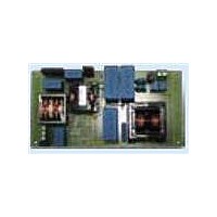
BOARD EVAL L6562AT L6599AT
Manufacturer
STMicroelectronics
Specifications of EVL130W-STRLIG
Current - Output / Channel
2.7A
Outputs And Type
1, Isolated
Voltage - Output
48V
Features
EN55022 class B compliant
Voltage - Input
85 ~ 305 V
Utilized Ic / Part
L6562AT, L6599AT
Description/function
SMPS for LED Street Lighting Applications
Data Bus Width
4 bit
Maximum Clock Frequency
30 MHz
Maximum Power Dissipation
130 W
Operating Supply Voltage
85 V to 305 V
Operating Voltage
48 V
Product
Display Modules
Lead Free Status / RoHS Status
Lead free / RoHS Compliant
For Use With/related Products
L6562AT, L6599AT
Other names
497-10541
Available stocks
Company
Part Number
Manufacturer
Quantity
Price


Main characteristics and circuit description
1.5
1.6
8/35
All demonstration boards implement the voltage loop circuitry previously described but in
case a current loop is also required, it can be achieved by implementing the following
modifications:
●
●
●
With these modifications the circuit is able to keep the output current constant at 2.7 A down
to an output voltage value around 30 V. This function can be used to optimize the voltage
drop and power dissipation in case current linear regulators are used to regulate the current
flowing in each LED strip. If the output current is lower, the voltage loop will take over the
operation, regulating the output voltage at its nominal value as when using the TS2431AILT.
Overload and short-circuit protection
The current flowing into the primary winding, proportional to the output load, is sensed by
the lossless circuit C34, R53, D19, D18, R57, and C35 and it is fed into the ISEN pin (#6) of
L6599AT. In case of overcurrent, the voltage on the pin will exceed an internal threshold (0.8
V), triggering a protection sequence. The capacitor (C21) connected to the DELAY pin (#2)
is charged by an internal 150 µA current generator. If the voltage on the pin reaches 2 V, the
soft-start capacitor is completely discharged so that the switching frequency is pushed to its
maximum value. As the voltage on the pin exceeds
3.5 V the IC stops switching and the internal generator is turned off, so that the voltage on
the DELAY pin will decay because of the external resistor connected between the pin and
GND. The L6599AT will be soft-restarted as the voltage drops below 0.3 V. In this way, under
short-circuit conditions, the converter will work intermittently with low input average power
and thus limiting the stress of components during shorts.
Overvoltage and open loop protection
Both circuit stages, PFC and resonant, are equipped with their own overvoltage protections.
The PFC controller L6562AT implements an overvoltage protection against the output
voltage variation occurring in case of transients, due to the poor bandwidth of the error
amplifier. Unfortunately it cannot protect the circuit in case of a feedback loop failure like
disconnection or deviation from the nominal value of the feedback loop divider. If a similar
failure condition is detected, the L6599AT pin DIS (#8) stops the operation and also stops
the PFC operation by means of the L6599AT pin PFC_STOP (#9) connected to the L6562AT
pin INV (#1). The converter operation will be latched until the V
discharged, then a new startup sequence will automatically take place and the converter will
resume operation if the failure is removed or a new sequence is triggered. The same
sequence occurs also in case of input voltage transients that may damage the converter.
The DIS pin is also used to protect the resonant stage against loop failures. The Zener
diode D17 detects the auxiliary voltage generated by the LLC transformer. In case a loop
failure occurs, it conducts and the voltage on pin DIS exceeds the internal threshold,
latching off the device. The L6562AT operation will be stopped too by the PFC_STOP pin,
like in the previous case and then after some time the circuit will restart.
Replace R30 and R31 0R0 Ω resistors with sensing resistors, 0R033 and 0R039
respectively, both 0805
Populate on PCB U4 and the relevant components shown on the schematic as N.M:
C36 = 1N0-0805; C37 = 100NF-0805; R51 = 15R-0805; R56 = 1K0-0805;
R6 = 22K-1206; C41 = 2N2-0805; U5 = SEA05TR
Remove TS2431AILT
Doc ID 16775 Rev 1
CC
capacitors are
AN3106
Related parts for EVL130W-STRLIG
Image
Part Number
Description
Manufacturer
Datasheet
Request
R

Part Number:
Description:
BOARD EVAL L6562AT L6599AT
Manufacturer:
STMicroelectronics
Datasheet:
Part Number:
Description:
STMicroelectronics [RIPPLE-CARRY BINARY COUNTER/DIVIDERS]
Manufacturer:
STMicroelectronics
Datasheet:
Part Number:
Description:
STMicroelectronics [LIQUID-CRYSTAL DISPLAY DRIVERS]
Manufacturer:
STMicroelectronics
Datasheet:

Part Number:
Description:
BOARD EVAL FOR MEMS SENSORS
Manufacturer:
STMicroelectronics
Datasheet:
Part Number:
Description:
NPN TRANSISTOR POWER MODULE
Manufacturer:
STMicroelectronics
Datasheet:
Part Number:
Description:
TURBOSWITCH ULTRA-FAST HIGH VOLTAGE DIODE
Manufacturer:
STMicroelectronics
Datasheet:
Part Number:
Description:
Manufacturer:
STMicroelectronics
Datasheet:
Part Number:
Description:
DIODE / SCR MODULE
Manufacturer:
STMicroelectronics
Datasheet:
Part Number:
Description:
DIODE / SCR MODULE
Manufacturer:
STMicroelectronics
Datasheet:
Part Number:
Description:
Search -----> STE16N100
Manufacturer:
STMicroelectronics
Datasheet:
Part Number:
Description:
Search ---> STE53NA50
Manufacturer:
STMicroelectronics
Datasheet:
Part Number:
Description:
NPN Transistor Power Module
Manufacturer:
STMicroelectronics
Datasheet: