MCP651EV-VOS Microchip Technology, MCP651EV-VOS Datasheet - Page 11
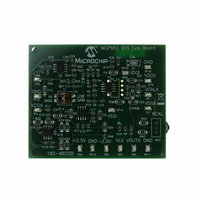
MCP651EV-VOS
Manufacturer Part Number
MCP651EV-VOS
Description
BOARD EVAL OP AMP MCP651
Manufacturer
Microchip Technology
Series
mCal Technologyr
Specifications of MCP651EV-VOS
Channels Per Ic
1 - Single
Amplifier Type
General Purpose
Output Type
Single-Ended, Rail-to-Rail
Slew Rate
30 V/µs
Current - Output / Channel
100mA
Operating Temperature
-40°C ~ 125°C
Current - Supply (main Ic)
6mA
Voltage - Supply, Single/dual (±)
2.5 V ~ 5.5 V
Board Type
Fully Populated
Utilized Ic / Part
MCP651
Processor To Be Evaluated
MCP651
Maximum Operating Temperature
+ 125 C
Minimum Operating Temperature
- 40 C
Operating Supply Voltage
2.5 V to 5.5 V
Tool Type
Evaluation Board
Core Architecture
PIC
Cpu Core
PIC
Data Bus Width
8 bit
Lead Free Status / RoHS Status
Lead free / RoHS Compliant
-3db Bandwidth
-
Lead Free Status / Rohs Status
Lead free / RoHS Compliant
Available stocks
Company
Part Number
Manufacturer
Quantity
Price
Company:

Part Number:
MCP651EV-VOS
Manufacturer:
Microchip Technology
Quantity:
135
Company:
Part Number:
MCP651EV-VOS
Manufacturer:
MICROCHIP
Quantity:
12 000


TABLE 1-2:
© 2009 Microchip Technology Inc.
R1, R2
R3
R4
R5, R6
R7, R8
C2
U1
U2
R11, R12
R13, R14
U3, R11, R12, C6
U3, R17, C7
U4, R23, R24, R25, R26, S2
R28, C12
Note 1:
Complete Schematic
Components
Switch S2’s top position is closed when to the right (LOW GAIN), and is open when to the left (HI GAIN).
CONVERSION OF SCHEMATIC COMPONENTS
1.4.2
Figure 1-2 is a simplified diagram of the circuitry that biases the DUT and produces an
amplified version of the DUT’s input offset voltage (V
a Proportional plus Integral (PI) controller loop, a high gain amplifier and a filter.
FIGURE 1-2:
The elements of Figure 1-2 correspond to the components in the complete schematic
(A.3 “Board – Schematic”) as follows.
V
M
Simplified Schematic
“Lowpass Filter (ω
Lowpass
Simplified Circuit and Operation
Filter
“Integrator (ω
Component
“+1 Buffer” —
Simplified Circuit.
“1/G
+2.5V
-2.5V
“DUT” —
INT
G
“G
BW
M
R
R
R
INT
/s)” ω
R
R
C
M
12
56
78
)” ω
3
4
2
” = R11 / (R11 + R12)
” = 1 + R24 / R23
ω
= R1 || R2
= R3
= R4
= R5 + R6
= R7 + R8
= C2
= R13 / (R13 + R14)
= 1 + (R24 + R25 + R26) / R23
INT
INT
BW
R
= 1 / (R17 · C7)
= 1 / ((R11 || R12)C6)
= 1 / (R28 · C12)
56
V
Conversion
Equations
Integrator
CMX
(ω
+2.5V
INT
-2.5V
= 0V
/s)
R
R
3
4
OST
R
DUT
R
). It includes gain at the input,
12
C
78
2
1/G
1/G
—
—
≈ 196.1Ω
≈ 200.0Ω
≈ 10.00 kΩ
≈ 8.04 kΩ
≈ 40.0 kΩ
≈ 22 nF
≈ 1 / (3.213 V/V)
≈ 1 / (3.213 V/V)
≈ 2π (10.3 Hz)
≈ 2π (10.4 Hz)
≈ 3.941 V/V, S2 closed
≈ 39.18 V/V, S2 open
≈ 2π (1.59 Hz)
INT
INT
Typical Values
+2.5V
(Note 1)
-2.5V
DS51834A-page 7
V
V
V
+1
DDI
OUTX
SSI
V
COX
Related parts for MCP651EV-VOS
Image
Part Number
Description
Manufacturer
Datasheet
Request
R

Part Number:
Description:
Manufacturer:
Microchip Technology Inc.
Datasheet:
Part Number:
Description:
Manufacturer:
Microchip Technology Inc.
Datasheet:
Part Number:
Description:
Manufacturer:
Microchip Technology Inc.
Datasheet:
Part Number:
Description:
Manufacturer:
Microchip Technology Inc.
Datasheet:
Part Number:
Description:
Manufacturer:
Microchip Technology Inc.
Datasheet:
Part Number:
Description:
Manufacturer:
Microchip Technology Inc.
Datasheet:
Part Number:
Description:
Manufacturer:
Microchip Technology Inc.
Datasheet:
Part Number:
Description:
Manufacturer:
Microchip Technology Inc.
Datasheet: