MCP651EV-VOS Microchip Technology, MCP651EV-VOS Datasheet - Page 21
MCP651EV-VOS
Manufacturer Part Number
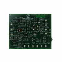
MCP651EV-VOS
Description
BOARD EVAL OP AMP MCP651
Manufacturer
Microchip Technology
Series
mCal Technologyr
Specifications of MCP651EV-VOS
Channels Per Ic
1 - Single
Amplifier Type
General Purpose
Output Type
Single-Ended, Rail-to-Rail
Slew Rate
30 V/µs
Current - Output / Channel
100mA
Operating Temperature
-40°C ~ 125°C
Current - Supply (main Ic)
6mA
Voltage - Supply, Single/dual (±)
2.5 V ~ 5.5 V
Board Type
Fully Populated
Utilized Ic / Part
MCP651
Processor To Be Evaluated
MCP651
Maximum Operating Temperature
+ 125 C
Minimum Operating Temperature
- 40 C
Operating Supply Voltage
2.5 V to 5.5 V
Tool Type
Evaluation Board
Core Architecture
PIC
Cpu Core
PIC
Data Bus Width
8 bit
Lead Free Status / RoHS Status
Lead free / RoHS Compliant
-3db Bandwidth
-
Lead Free Status / Rohs Status
Lead free / RoHS Compliant
Available stocks
Company
Part Number
Manufacturer
Quantity
Price
Company:

Part Number:
MCP651EV-VOS
Manufacturer:
Microchip Technology
Quantity:
135
Company:
Part Number:
MCP651EV-VOS
Manufacturer:
MICROCHIP
Quantity:
12 000


2.6
© 2009 Microchip Technology Inc.
SETTLING TIME, NOISE AND SAMPLING RATE
The bandwidth seen by the signal (DUT’s V
input and VM, is set mainly by the lowpass filter at the VM test point (TP5); this
bandwidth is about 1.6 Hz. This bandwidth sets the settling time seen at VM (after the
DUT’s bias point has been changed) to about 0.6 seconds.
The noise seen in the measurements is a result of DUT’s input noise voltage passed
through the same 1.6 Hz lowpass filter. The MCP651’s 1/f noise dominates at such low
frequencies, so V
1/f wander can be estimated to be roughly:
• 5 µV
• 34 µV
Averaging several measurements together will help reduce the noise over a short
period of time. It must be understood, however, that the 1/f noise will make V
appear to change over long periods of time.
There is a practical limit on increasing the sample rate; the noise does not improve
significantly after a certain point. The analog lowpass pole at 1.6 Hz causes closely
spaced samples to be correlated. To avoid the overhead caused by sampling too fast,
keep the sampling period near or above the pole’s time constant (0.10s); this gives a
minimum sample rate of 10 samples per second.
Note:
P-P
P-P
for a time period of 1 second
Sampling much faster than 10 SPS will not improve the averaged noise
significantly.
for a time period of 10 years
OST
will appear to wander over time. The standard deviation of this
OST
and noise voltage), between the DUT’s
DS51834A-page 17
OST
Related parts for MCP651EV-VOS
Image
Part Number
Description
Manufacturer
Datasheet
Request
R

Part Number:
Description:
Manufacturer:
Microchip Technology Inc.
Datasheet:
Part Number:
Description:
Manufacturer:
Microchip Technology Inc.
Datasheet:
Part Number:
Description:
Manufacturer:
Microchip Technology Inc.
Datasheet:
Part Number:
Description:
Manufacturer:
Microchip Technology Inc.
Datasheet:
Part Number:
Description:
Manufacturer:
Microchip Technology Inc.
Datasheet:
Part Number:
Description:
Manufacturer:
Microchip Technology Inc.
Datasheet:
Part Number:
Description:
Manufacturer:
Microchip Technology Inc.
Datasheet:
Part Number:
Description:
Manufacturer:
Microchip Technology Inc.
Datasheet: