ADIS16240/PCBZ Analog Devices Inc, ADIS16240/PCBZ Datasheet - Page 10

ADIS16240/PCBZ
Manufacturer Part Number
ADIS16240/PCBZ
Description
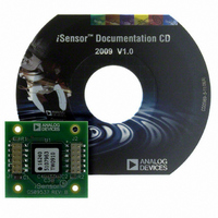
BOARD EVAL FOR ADIS16240
Manufacturer
Analog Devices Inc
Series
iMEMS®, iSensor™r
Specifications of ADIS16240/PCBZ
Sensor Type
Accelerometer, 3 Axis
Sensing Range
±19g
Interface
SPI Serial
Sensitivity
51.4mg/LSB
Voltage - Supply
2.4 V ~ 3.6 V
Embedded
No
Utilized Ic / Part
ADIS16240
Silicon Manufacturer
Analog Devices
Application Sub Type
Shock Sensor
Kit Application Type
Sensing - Motion / Vibration / Shock
Silicon Core Number
ADIS16240
Lead Free Status / RoHS Status
Lead free by exemption / RoHS compliant by exemption
ADIS16240
MEMORY MAP
Note that all registers are two bytes. All unused memory locations are reserved for future use.
Table 7. User Register Memory Map
Register
Name
FLASH_CNT
SUPPLY_OUT
XACCL_OUT
YACCL_OUT
ZACCL_OUT
AUX_ADC
TEMP_OUT
XPEAK_OUT
YPEAK_OUT
ZPEAK_OUT
XYZPEAK_OUT
CAPT_BUF1
CAPT_BUF2
DIAG_STAT
EVNT_CNTR
CHK_SUM
XACCL_OFF
YACCL_OFF
ZACCL_OFF
CLK_TIME
CLK_DATE
CLK_YEAR
WAKE_TIME
WAKE_DATE
ALM_MAG1
ALM_MAG2
ALM_CTRL
XTRIG_CTRL
CAPT_PNTR
CAPT_CTRL
GPIO_CTRL
MSC_CTRL
SMPL_PRD
GLOB_CMD
1
Each register contains two bytes. The address of the lower byte is displayed. The address of the upper byte is equal to the address of the lower byte plus 1.
DOUT
SCLK
NOTES
1. DOUT BITS ARE BASED ON THE PREVIOUS 16-BIT SEQUENCE, WHEN R/W = 0.
DIN
CS
R/W
Read/
Write
R
R
R
R
R
R
R
R
R
R
R
R
R
R
R
R
R/W
R/W
R/W
R/W
R/W
R/W
R/W
R/W
R/W
R/W
R/W
R/W
R/W
R/W
R/W
R/W
W
D15
R/W
Flash
Backup
Yes
No
No
No
No
No
No
No
No
No
No
Yes
Yes
Yes
Yes
Yes
Yes
Yes
Yes
Yes
Yes
Yes
Yes
Yes
Yes
Yes
No
No
Yes
Yes
D14
A6
D13
A5
D12
A4
Register
Address
0x00
0x02
0x04
0x06
0x08
0x0A
0x0C
0x0E
0x10
0x12
0x14
0x16
0x18
0x1A
0x1C
0x1E
0x20
0x22
0x24
0x2E
0x30
0x32
0x34
0x36
0x38
0x3A
0x3C
0x3E
0x40
0x42
0x44
0x46
0x48
0x4A
D11
A3
D10
A2
1
Figure 18. SPI Communication Bit Sequence
A1
D9
Default
N/A
N/A
N/A
N/A
N/A
N/A
N/A
N/A
N/A
N/A
N/A
N/A
N/A
0x0000
0x0000
N/A
0x0000
0x0000
0x0000
0x0000
0x0000
0x0000
0x0000
0x0000
0x9000
0x9000
0x0000
0x0000
0x0000
0x0022
0x0000
0x0006
0x001F
N/A
A0
D8
Rev. 0 | Page 10 of 16
DC7 DC6 DC5 DC4 DC3 DC2 DC1 DC0
D7
Function
Flash memory write count
Output, power supply
Output, x-axis accelerometer
Output, y-axis accelerometer
Output, z-axis accelerometer
Output, auxiliary ADC input
Output, temperature
Output, x-axis acceleration peak
Output, y-axis acceleration peak
Output, z-axis acceleration peak
Output, sum-of-squares acceleration peak
Output, Capture Buffer 1, X and Y acceleration
Output, Capture Buffer 2, Z acceleration
Diagnostic, error flags
Diagnostic, event counter
Diagnostic, check sum value from firmware test
Calibration, x-axis acceleration offset adjustment
Calibration, y-axis acceleration offset adjustment
Calibration, z-axis acceleration offset adjustment
Clock, hour and minute
Clock, month and day
Clock, year
Wake-up setting, hour and minute
Wake-up setting, month and day
Alarm 1 amplitude threshold
Alarm 2 amplitude threshold
Alarm control
Capture, external trigger control
Capture, address pointer
Capture, configuration and control
General-purpose digital input/output control
Miscellaneous control
Internal sample period (rate) control
System command
D6
D5
D4
D3
D2
D1
D0
D15
R/W
D14
A6
D13
A5
Bit
Assignments
N/A
See Table 10
See Table 9
See Table 9
See Table 9
See Table 8
See Table 11
See Table 9
See Table 9
See Table 9
See Table 8
See Table 18
See Table 19
See Table 28
See Table 21
See Table 34
See Table 27
See Table 27
See Table 27
See Table 29
See Table 30
See Table 31
See Table 32
See Table 33
See Table 13
See Table 13
See Table 12
See Table 15
See Table 20
See Table 17
See Table 26
See Table 25
See Table 23
See Table 24


