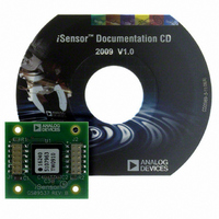
ADIS16240/PCBZ Analog Devices Inc, ADIS16240/PCBZ Datasheet - Page 8

ADIS16240/PCBZ
Manufacturer Part Number
ADIS16240/PCBZ
Description
BOARD EVAL FOR ADIS16240
Manufacturer
Analog Devices Inc
Series
iMEMS®, iSensor™r
Specifications of ADIS16240/PCBZ
Sensor Type
Accelerometer, 3 Axis
Sensing Range
±19g
Interface
SPI Serial
Sensitivity
51.4mg/LSB
Voltage - Supply
2.4 V ~ 3.6 V
Embedded
No
Utilized Ic / Part
ADIS16240
Silicon Manufacturer
Analog Devices
Application Sub Type
Shock Sensor
Kit Application Type
Sensing - Motion / Vibration / Shock
Silicon Core Number
ADIS16240
Lead Free Status / RoHS Status
Lead free by exemption / RoHS compliant by exemption
ADIS16240
THEORY OF OPERATION
The ADIS16240 is a triple-axis accelerometer system for shock
detection and recording applications. This sensing system collects
data autonomously and makes it available to any processor system
that supports a 4-wire serial peripheral interface (SPI).
SENSING ELEMENT
Digital shock sensing starts with the triple-axis MEMS sensing
element in the ADIS16240. This element provides a linear motion-
to-electrical transducer function. Figure 11 provides a basic
physical diagram of the sensing element and its response to
linear acceleration. It uses a fixed frame and a moving frame to
form a differential capacitance network that responds to linear
acceleration. Tiny springs tether the moving frame to the fixed
frame and govern the relationship between acceleration and
physical displacement. A modulation signal on the moving plate
feeds through each capacitive path into the fixed frame plates
and into a demodulation circuit, which produces the electrical
signal that is proportional to the acceleration acting on the device.
DATA SAMPLING AND PROCESSING
The analog acceleration signals feed into an analog-to-digital
converter stage that passes digitized data into the controller for
data processing and capture. The ADIS16240 runs autonomously,
based on the configuration in the user control registers.
SENSOR
MEMS
CAPACITORS
UNIT SENSING
CELL
Figure 12. Simplified Sensor Signal Processing Diagram
CLOCK
PLATE
Figure 11. MEMS Sensor Diagram
INPUT/OUTPUT
CONTROLLER
FUNCTIONS
CAPTURE
BUFFER
MOVING
PLATE
ANCHOR
ANCHOR
FIXED
PLATES
REGISTERS
REGISTERS
CONTROL
OUTPUT
MOVABLE
FRAME
UNIT
FORCING
CELL
Rev. 0 | Page 8 of 16
USER INTERFACE
SPI Interface
Data collection and configuration commands both use the SPI,
which consists of four wires. The chip select ( CS ) signal activates
the SPI interface, and the serial clock (SCLK) synchronizes the
serial data lines. The serial input data clocks into DIN on the rising
edge of SCLK, and the serial output data clocks out of DOUT on
the falling edge of SCLK. Many digital processor platforms
support this interface with dedicated serial ports and simple
instruction sets.
User Registers
The user registers provide addressing for all input/output
operations on the SPI interface. Each 16-bit register has its own
unique bit assignment and has two 7-bit addresses: one for its
upper byte and one for its lower byte. Table 7 provides a memory
map for each register and identifies output registers as read only
(R) and configuration registers as either read/write (R/W) or write
only (W). The control registers use a dual-memory structure. The
SRAM controls operation while the part is on and facilitates all user
configuration inputs. The flash memory provides nonvolatile stor-
age for the control registers that are identified with a “yes” in the
flash backup column in Table 7. Storing configuration data in the
flash memory requires a manual command (see GLOB_CMD[3]
in Table 24). When the device starts up from an initial power-up
or reset, the flash memory contents load into the SRAM. Then
the device starts producing data according to the configuration
in the control registers.
CAPTURE
The ADIS16240 offers a recorder function that captures
acceleration information based on either internal or external
triggers. The buffer memory is 3 × 8192 samples and is capable
of storing multiple trigger events.
Figure 13. Control Registers—SRAM and Flash Memory Diagram
(NO SPI ACCESS)
FLASH MEMORY
NONVOLATILE
START-UP
MANUAL
BACKUP
FLASH
RESET
(SPI ACCESS)
VOLATILE
SRAM


