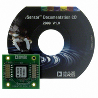
ADIS16240/PCBZ Analog Devices Inc, ADIS16240/PCBZ Datasheet - Page 12

ADIS16240/PCBZ
Manufacturer Part Number
ADIS16240/PCBZ
Description
BOARD EVAL FOR ADIS16240
Manufacturer
Analog Devices Inc
Series
iMEMS®, iSensor™r
Specifications of ADIS16240/PCBZ
Sensor Type
Accelerometer, 3 Axis
Sensing Range
±19g
Interface
SPI Serial
Sensitivity
51.4mg/LSB
Voltage - Supply
2.4 V ~ 3.6 V
Embedded
No
Utilized Ic / Part
ADIS16240
Silicon Manufacturer
Analog Devices
Application Sub Type
Shock Sensor
Kit Application Type
Sensing - Motion / Vibration / Shock
Silicon Core Number
ADIS16240
Lead Free Status / RoHS Status
Lead free by exemption / RoHS compliant by exemption
ADIS16240
EVENT RECORDER
The ADIS16240 provides a 3 × 8192 (8-bit) buffer memory for
reading transient acceleration data on all three axes (x, y, and z).
There are a number of user controls for tailoring the event recorder
for optimal system-level operation. Alarm 1 and Alarm 2 provide
internal and external trigger options for starting a data capture
sequence.
Internal Trigger Setup
Select the trigger data source for Alarm 1 and Alarm 2 using
ALM_CTRL[15:8] (see Table 12). The ALM_MAG1 and ALM_
MAG2 registers contain threshold magnitude and direction
settings for Alarm 1 and Alarm 2, respectively. The format for
the data bits in these registers matches the trigger data source,
which is set using ALM_CTRL[15:8]. For example, if ALM_
CTRL[15:12] equals 0010, then the format matches that of
XACCL_OUT: 10-bit, twos complement, with 1 LSB = 51.4 mg
of acceleration.
Table 12. ALM_CTRL Register Bit Descriptions
Bit
[15:12]
[11:8]
[7:6]
5
4
3
2
1
0
1
Table 13. ALM_MAG1, ALM_MAG2 Register Bit Descriptions
Bit
15
14
[13:0]
1
The ALM_CTRL register is located at Address 0x3D[15:8] and Address 0x3C[7:0].
The ALM_MAG1 register is located at Address 0x39[15:8] and Address 0x38[7:0].
The ALM_MAG2 register is located at Address 0x3B[15:8] and Address 0x3A[7:0].
Description (Default = 0x0000)
Alarm 2 source selection
0000 = disabled
0001 = power supply voltage (SUPPLY_OUT)
0010 = x acceleration (XACCL_OUT)
0011 = y acceleration (YACCL_OUT)
0100 = z acceleration (ZACCL_OUT)
0101 = auxiliary ADC voltage (AUX_ADC)
0110 = temperature (TEMP_OUT)
0111 = XYZ peak acceleration (XYZPEAK_OUT)
1000 = external trigger
Alarm 1 source selection (same as Alarm 2)
Unused
Alarm 2 capture trigger: 1 = enabled, 0 = disabled
Alarm 1 capture trigger: 1 = enabled, 0 = disabled
Unused
Alarm indicator enable: 1 = enabled, 0 = disabled
Alarm indicator polarity: 1 = positive, 0 = negative
Alarm indicator pin: 1 = DIO2, 0 = DIO1
Description (Default = 0x9000)
Threshold direction
1 = active for output greater than alarm magnitude
0 = inactive for output less than alarm magnitude
Unused
Trigger threshold; bit format matches that of the
register selected by ALM_CTRL[15:8] but is unsigned.
1
Rev. 0 | Page 12 of 16
1
Table 14. Internal Trigger Setup Example
DIN
0xBD44
0xB980,
0xBB00,
0xBC37
External Trigger Setup
ALM_CTRL[15:8] and XTRIG_CTRL (see Table 15) provide all
of the settings needed to govern the use of the comparator pins
(CMP1, CMP2) as external trigger inputs.
Table 15. XTRIG_CTRL Register Bit Descriptions
Bit
[15:8]
7
6
5
4
[3:0]
1
Table 16. External Trigger Setup Example
DIN
0xBD80
0xBE1C
0xBC20
If the device is in standby mode, an external trigger on CMD1 or
CMD2 awakens the device and initiates an event capture. The first
sample is taken 0.2 ms + sample period (SMPL_PRD[7:0]) after
the trigger edge.
Buffer Memory Configuration
CAPT_CTRL (see Table 17) manages the buffer memory for the
event recorder using two programmable controls: event length and
pretrigger length.
Table 17. CAPT_CTRL Register Bit Descriptions
Bit
[15:8]
[7:4]
3
[2:0]
1
The event length (N
that the buffer can store at one time.
The XTRIG_CTRL register is located at Address 0x3F[15:8] and Address 0x3E[7:0].
The CAPT_CTRL register is located at Address 0x43[15:8] and Address 0x42[7:0].
0xB832
0xBA0A
Description (Default = 0x0000)
External Trigger 1 enable: 1 = enabled, 0 = disabled
External Trigger 2 enable: 1 = enabled, 0 = disabled
Description
Set Alarm 2 to an external trigger (ALM_CTRL)
Activate and set CMP2 to trigger on signals that are
greater than one-half of the supply voltage (XTRIG_CTRL)
Activate Alarm 2 to trigger data capture (ALM_CTRL)
Description (Default = 0x0022)
Event length control factor (T), binary format
Unused
External Trigger 1 direction: 0 = <, 1 = >
External Trigger 2 direction: 0 = <, 1 = >
External trigger-level setting (TL), binary format
Note that trigger threshold = TL × supply/24
Unused
Pretrigger length control factor (P), binary format
Unused
Description
Set Alarm 1 and Alarm 2 to ZACCL_OUT
Set Alarm 1 to trigger on a measured acceleration
that has a magnitude of >2.57 g
Set Alarm 2 to trigger on a measured acceleration
that has a magnitude of <0.5 g
Activate Alarm 1 and Alarm 2 to trigger capture events,
and configure DIO2 as a positive alarm indicator output.
L
) also determines the number of events (N
1
1
E
)


